14-45
dummyheaddummyhead
CYLINDER HEAD
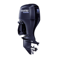
Measure the valve set width.
Make a light pass with the 45° cutter to remove any
possible burrs at the edges of the seat.
After resurfacing the seats, inspect for even valve
seating.
Apply Prussian Blue compound or erasable felt-tipped
marker ink to the valve faces. Insert the valves, and
then lift them and snap them closed against their seats
several times. Be sure the valve does not rotate on the
seat. The seating surface, as shown by the transferred
marking compound, should have good contact all the
way around.
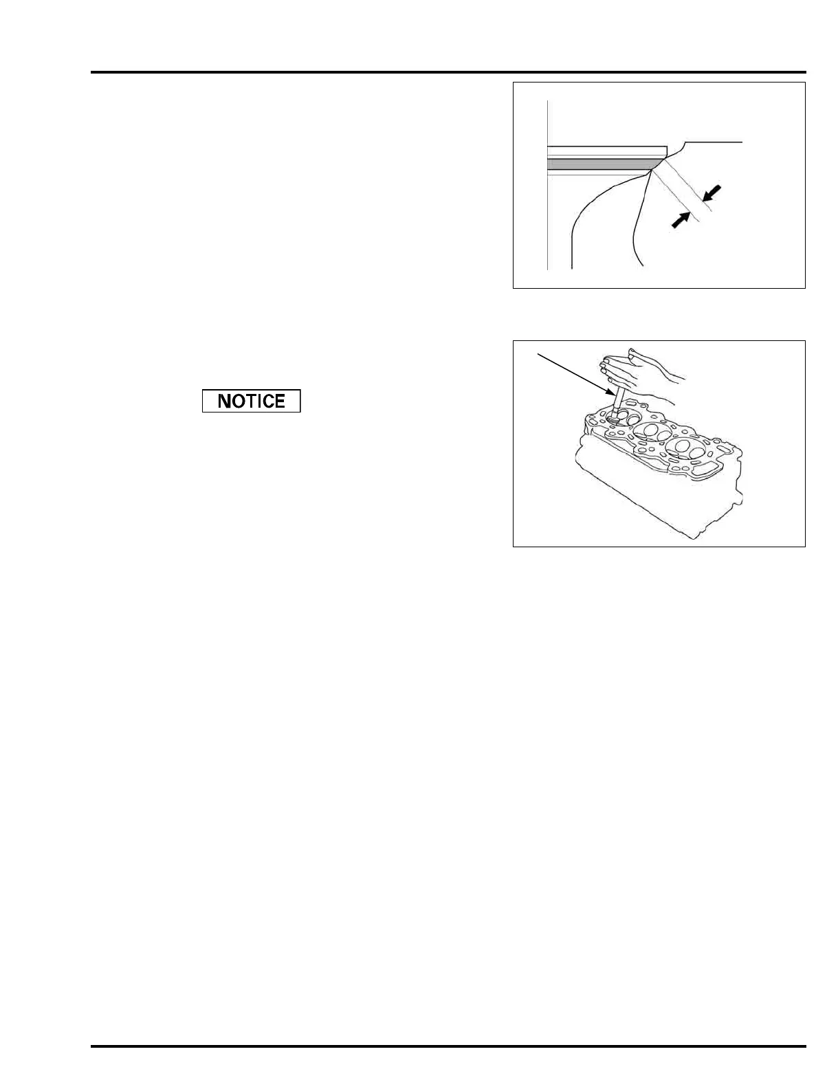
Lap the valves into their seats, using a hand valve
lapper (LIL-21100: commercially available) [1] and
lapping compound.
• To avoid severe engine damage, be sure to remove
all lapping compound from the cylinder head before
assembly.
Check valve clearance after assembly.
STANDARD:
1.25 – 1.55 mm (0.049 – 0.061 in)
SERVICE LIMIT:
2.0 mm (0.08 in)
1.25 – 1.55 mm
(0.049 – 0.061 in)
 Loading...