MC-X1 Connectivity and Configuration
Assigning GR-i3 Vibration Mount to Auxiliary
8
Excavator Indicate System P/N: 1022461-01
Assigning GR-i3 Vibration Mount to Auxiliary
The Main GR-i3 Vibration Mount must be disconnected from the system in order to assign an
Auxiliary (AUX) antenna.
1. Open 3D-MC to create a machine builder file (if one has not already been created), and select
MC-X1 from the Position input drop-down menu. If a machine builder has already been
configured, make sure MC-X1 is selected as the Position Input.
2. Navigate to the end of the machine builder, and tap Finish.
3. Ensure the correct machine file is selected on the Machine files page, and tap OK. Now, your
.mx3 is deployed, and the necessary sensors will populate in the MC-X Machine Control Gateway
Sensors menu.
4. Open MCXCONFIG.
5. Disconnect the CAN cable from the bottom of the Main GR-i3 Vibration Mount on the Left side of
the machine.
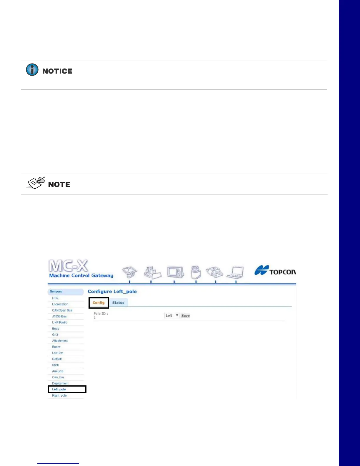
6. From the menus on the left of the screen, click Sensors > Left_pole, and then click the Config
tab..
Figure 12. Settings - Left Pole - Config Tab
7. Select Right from the drop-down menu (Figure 13).
If Left Pole, Right Pole, GRi3, or AuxGRi3 do not populate in the MC-X Machine
Control Gateway Sensors menu, 3DMC must deploy a machine file with MC-X1 as
Position input.
An .mx3 file that is active in 3D-MC is considered the “deployment”.