30
PREPARATIONS
3 Connect the other end of the connection cable to the PC, etc.
4 Replace the External I/O terminal cover.
IMAGEnet
1 Connect the connection cord to the LAN I/O terminal of the instrument.
2 Connect the other end of the connection cord to the IMAGEnet system.
DATA INPUT
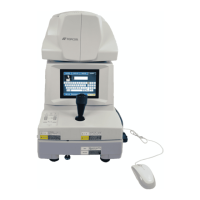
This product can be connected to a bar-code reader and other external devices via USB.
1 Connect the connection cable to the USB I/O terminal of the instrument.
2 Connect the other end of the connection cable to the external device.
NOTE
• The connection cord for IMAGEnet is an IMAGEnet optional accessory.
Prepare this cord prior to connection. For details on the IMAGEnet system,
contact your dealer (on the back cover).
• Do not insert or remove the LAN cable while the power of the instrument is
ON.
• Sometimes the connection is not done properly because of the character-
istics of the hardware. Use the LAN cable specified by TOPCON.
NOTE
• For questions about connections, contact your TOPCON dealer.
• When you use a hub, use the USB hub with power supply.