4. Attach the keyboard tray to the operator console with
two M3 Phillips screws (provided in the controller box)
and a Phillips screwdriver.
Figure 4-15: Attaching the keyboard tray to the
operator console (from below).
5. Put the operator console's power supply into the power
supply bracket (provided in the operator console box),
and attach the assembly to the underside of the
keyboard tray with M3 Phillips screws and a Phillips
screwdriver.
Figure 4-16: Attaching the operator console's power
supply and power supply bracket to the keyboard tray
(from below).
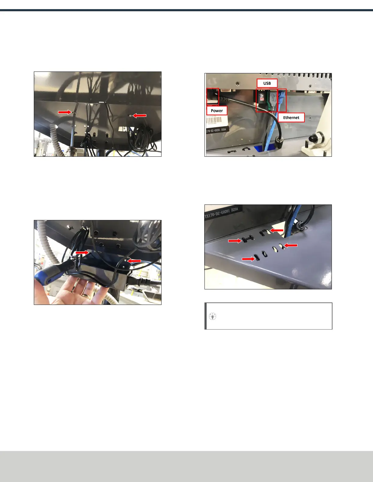
6. Connect the 12 ft power cable to the power supply.
7. Use the three pivot bolts on the controller arm monitor
bracket to adjust the position of the operator console
and the keyboard tray to your desired angle with an 3
mm hex wrench and 16 mm hex wrench.
8. If you have any of the following optional USB
accessories, connect them to the operator console:
l Jog shuttle
l Keyboard
l Mouse
l WiFi dongle
9. Connect the Ethernet cable to the operator console.
10. Connect the barrel end of the power supply cable to the
operator console.
Figure 4-17: USB accessories connected.
11. Route the loose ends of the USB, Ethernet, and power
supply cables through the square hole in the keyboard
tray. Then, use the cable tie holes to secure the loose
power supply and USBcables.
Figure 4-18: Cable tie holes.
Tip! We recommend that you leave some slack
for the mouse and jog shuttle cables.
©Tormach® 2021
Specifications subject to change without notice.
Page 30 UM10753: 8L Operator's Manual (Version 0321B)
For the most recent version, see tormach.com/support
4: INSTALLATION