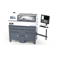
3. To attach the tool holder, the tool post must be in the
unlocked position: move the tool post handle up.
Figure 4-44: Quick change tool post positions.
4. Put the tool holder onto the tool post, and then move the
tool post handle down to the locked position.
5. Before operating the machine, you must make sure that
the quick change tool holder is aligned. Go to "Align the
Tool" (below).
To Use a Boring Bar
1. To attach the tool holder, the tool post must be in the
unlocked position: move the tool post handle up.
2. Put the tool into the boring bar holder.
3. Put the tool holder onto the tool post, and then move the
tool post handle down to the locked position.
4. Lock the tool into the tool holder: tighten its two hex
head screws.
Figure 4-45: Boring bar installed in a boring bar tool
holder.
Tip! When you remove the tool, loosen the hex
head screws, and gently tap them with a dead-
blow hammer.
Align the Tool
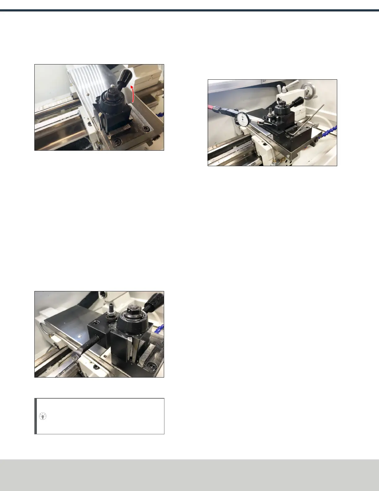
1. Attach a magnetic dial test indicator to the spindle.
2. Put the indicator tip on the face of the tool holder.
Figure 4-46: Magnetic dial test indicator on the face
of the tool holder.
3. Power on the machine and the PathPilot controller.
a. Turn the Main Disconnect switch to ONon the side of
the electrical cabinet.
b. Twist out the Emergency Stop button on the operator
box, which enables movement to the machine axes
and the spindle.
c. Press the Reset button on the operator box.
d. Bring the machine out of reset and reference it.
4. Slowly jog the machine along the X-axis to move the
indicator tip along the face of the tool.
©Tormach® 2021
Specifications subject to change without notice.
Page 38 UM10753: 8L Operator's Manual (Version 0321B)
For the most recent version, see tormach.com/support
4: INSTALLATION