7: TROUBLESHOOTING
©Tormach® 2021
Specifications subject to change without notice.
Page 76 UM10753: 8L Operator's Manual (Version 0321B)
For the most recent version, see tormach.com/support
Cause: The motor is defective.
Probability How-To Steps Need More?
Low
1. Power off the machine (see "Power Off the Machine" (page35)).
2. Wait 30 seconds, and then remove wires 118, 119, and 120 from the
VFDterminals.
3. Measure the resistance between:
l Wires 118 and 119
l Wires 119 and 120
l Wires 120 and 118
Resistance should be in the range of approximately 2-4 Ω.
l 0 Ω indicates that the winding is
shorted.
l >1M Ω indicates that the
winding is open.
Both cases indicate a defective
motor or compromised wiring to
the motor from the VFD.
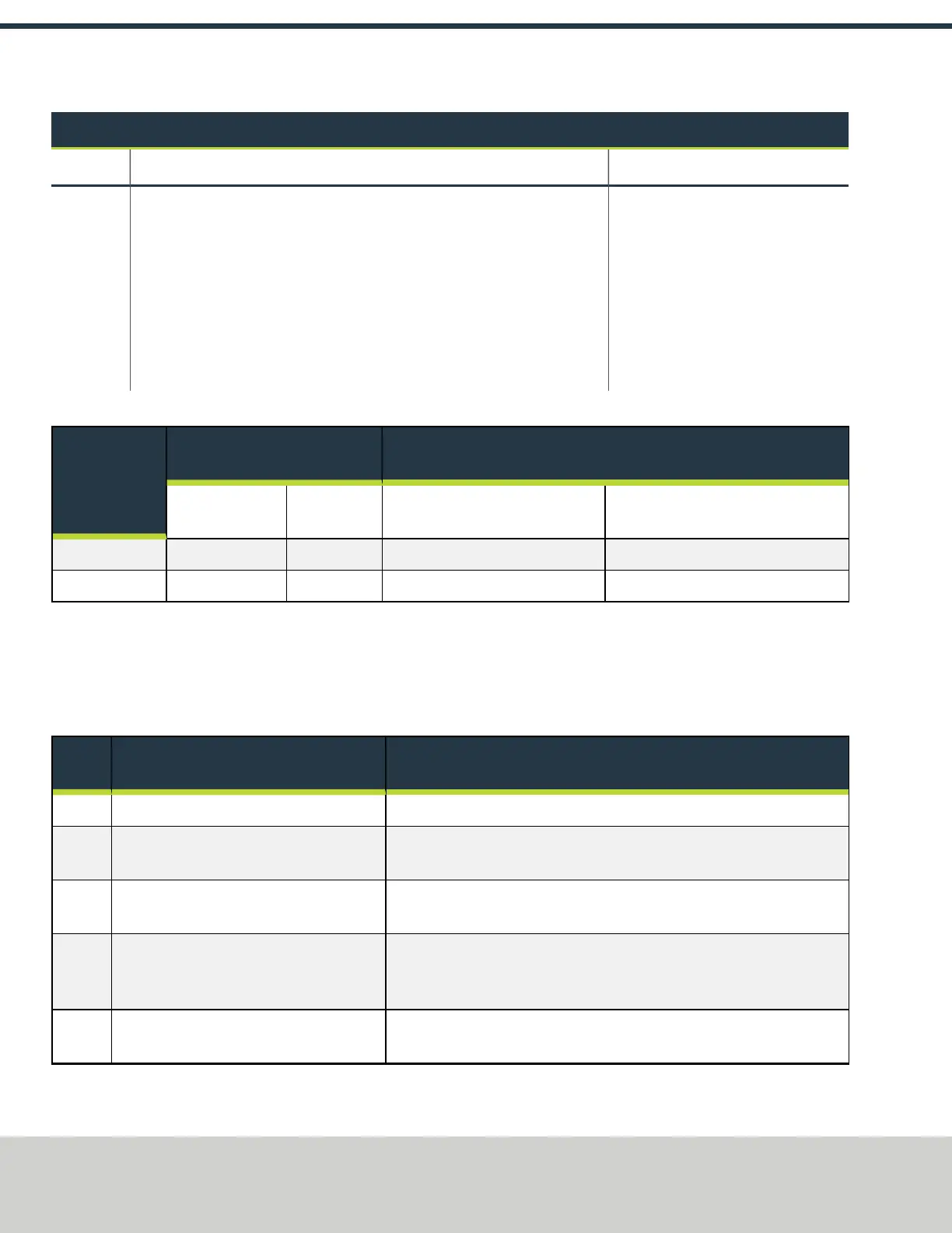
Run and Direction Commands Reference
Command From
Card
Monitoring Points One Probe on
Each
Voltage Measured
Common wire
number
Wire number Voltage when control board
command is on
Voltage when control board command
is not on
Run (FWD) 403 404 14-20 Vdc 0 Vdc
Reverse 403 406 14-20 Vdc 0 Vdc
The display on the VFD provides valuable information for troubleshooting. The display diagnostics include:
l Frequency output (proportional to speed. Range is ~7 Hz to 142 Hz).
l Status (rd for ready, inh for inhibit which will occur when there is no jumper between terminals B2 and B4 on the drive).
l Fault information (Er for trip) and a code for the fault.
Spindle VFD Trip Reference
Trip
Code
Condition Likely Cause
UU DC-BUS under-voltage. This happens when the VFD is powered down.
OU DC-BUS over-voltage. Braking resistor failed open or wiring connection open between the VFD and
the resistor. Resistance to measure 70 ohms.
OI.AC VFD output instantaneous over current. Phase to phase or phase to ground short on output of VFD to motor. This trip
code cannot be reset until 10 seconds after the trip was initiated.
OI.br Braking resistor instantaneous over current. Braking resistor shorted or partially shorted out or short in wiring between the
VFD and the resistor. Resistance to measure 70 ohms. Check brake resistor
wiring.
It.br I
2
t (power) on braking resistor. Excessive braking resistor energy caused by too frequent and too severe
deceleration cycles or AC supply voltage too high.