Work Offset Naming
10 G54.1 P10 Not used
11 G54.1 P11 Not used
...
499 G54.1 P499 Not used
500 G54.1 P500 Not used
6.9 SET TOOL GEOMETRY OFFSETS
Before running a G-code program, PathPilot must know the
geometry of the tools that are required for the program. For
more information on using tool length offsets, see "About Tool
Offsets" (on the next page).
Note: You can import a .csv file with tool geometry
offset data. For information, see "Import and Export
the Tool Table" (on the next page).
To set tool geometry offsets:
1. Verify that the machine is powered on, out of reset, and
the axes have been referenced.
2. From the PathPilot controller, on the Offsets tab, select
the Offsets Table tab.
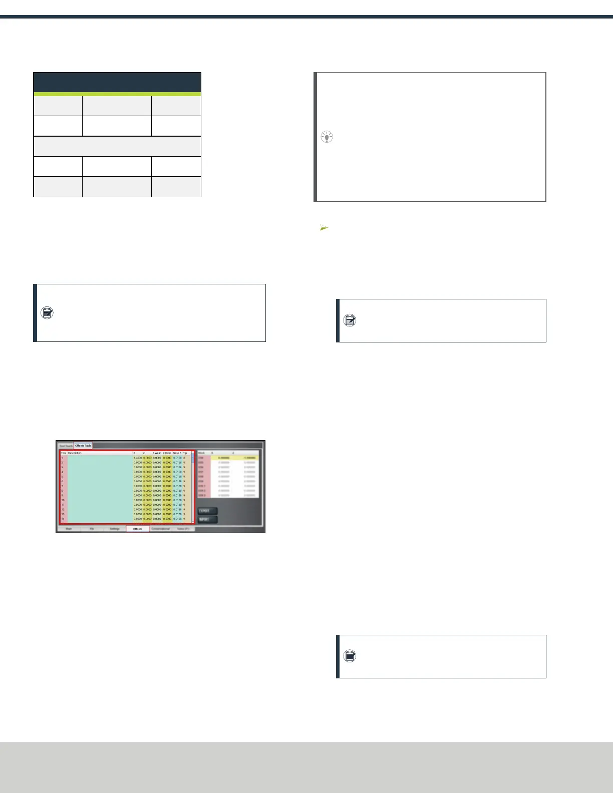
3. Find the Tool Table window.
Figure 6-16: Tool Table window on the Offsets tab.
4. Touch off the tool geometry offsets. For information, see
"Touch Off the Tool Geometry Offsets" (below).
5. (Optional) Select a field to edit. When finished, select
the Enter key.
6.9.1 Touch Off the Tool Geometry Offsets
On the Offsets tab, you can use the Tool Touch tab to
graphically select a tool, and then touch off the tool to set the
geometry offsets.
Tip! When using this method to measure your tool
geometry, remember that the X zero location never
changes (the spindle centerline is always X = 0), but
the Z zero location may change depending on the
length of the workpiece that is chucked into the
spindle. As long as each tool is measured to a face
that has been zeroed, only measure these tools one
time or until you replace an insert.
To touch off the tool geometry offsets:
From the Offsets tab, on the Tool Touch tab, select a
tool.
The tools along the bottom of the screen are front tool
post tools (used by machines with a quick-change tool
post setup).
Note: Gang tooling setups typically use both
front and rear tool post tools.
After you select the tool, PathPilot:
o
Sets the tip orientation for the tool, used (along with
tip radius) in cutter compensation.
o
Sets the tool type (front tool post or rear tool post),
used by the conversational routines to double check
the user entry fields in an attempt to try to detect and
prevent crashes.
o
Displays the tool touch off dialog.
Touch X
1. Take a skim cut off of the diameter of the workpiece —
just long enough to measure the cut surface with a
micrometer.
2. Jog the tool away from workpiece in Z, but don't jog the
machine in X.
3. Measure the diameter of the skim-cut workpiece with a
micrometer.
4. In the Touch XDROfield, type the value that you
measured in Step 3.
Note: If you're touching off a front tool post
tool, verify that the value you enter is negative.
5. Select Touch X.
The LEDcomes on.
©Tormach® 2021
Specifications subject to change without notice.
Page 50 UM10753: 8L Operator's Manual (Version 0321B)
For the most recent version, see tormach.com/support
6: BASIC OPERATIONS