4: INSTALLATION
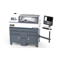
12. Connect the jog pendant cable and the Emergency Stop
cable to the operator console. Route the loose end of the
Emergency Stop cable through the round hole in the
keyboard tray.
Figure 4-19: Jog pendant (left) and Emergency Stop
(right) cables connected.
13. Route the loose end of the operator console's 12 ft
power cable, the Emergency Stop cable, and the
Ethernet cable down the controller arm. Then, route the
cables through the slots in the square tube arm that's
connected to the machine stand.
14. On the right side of the machine, connect the loose ends
of the cables as follows:
a. Connect the operator console's power cable to any of
the Accessory power outlets.
b. Connect the Ethernet cable to the Controller
Communications port.
c. Connect the Emergency Stop cable to the Emergency
Stop port.
15. Secure the cables to the wire tie mounts that you
installed on the round monitor post with four 4 in. cable
ties.
WARNING! Electrical Shock Hazard: You must
power off the machine before making any
electrical connections. If you don't, there's a
risk of electrocution or shock.
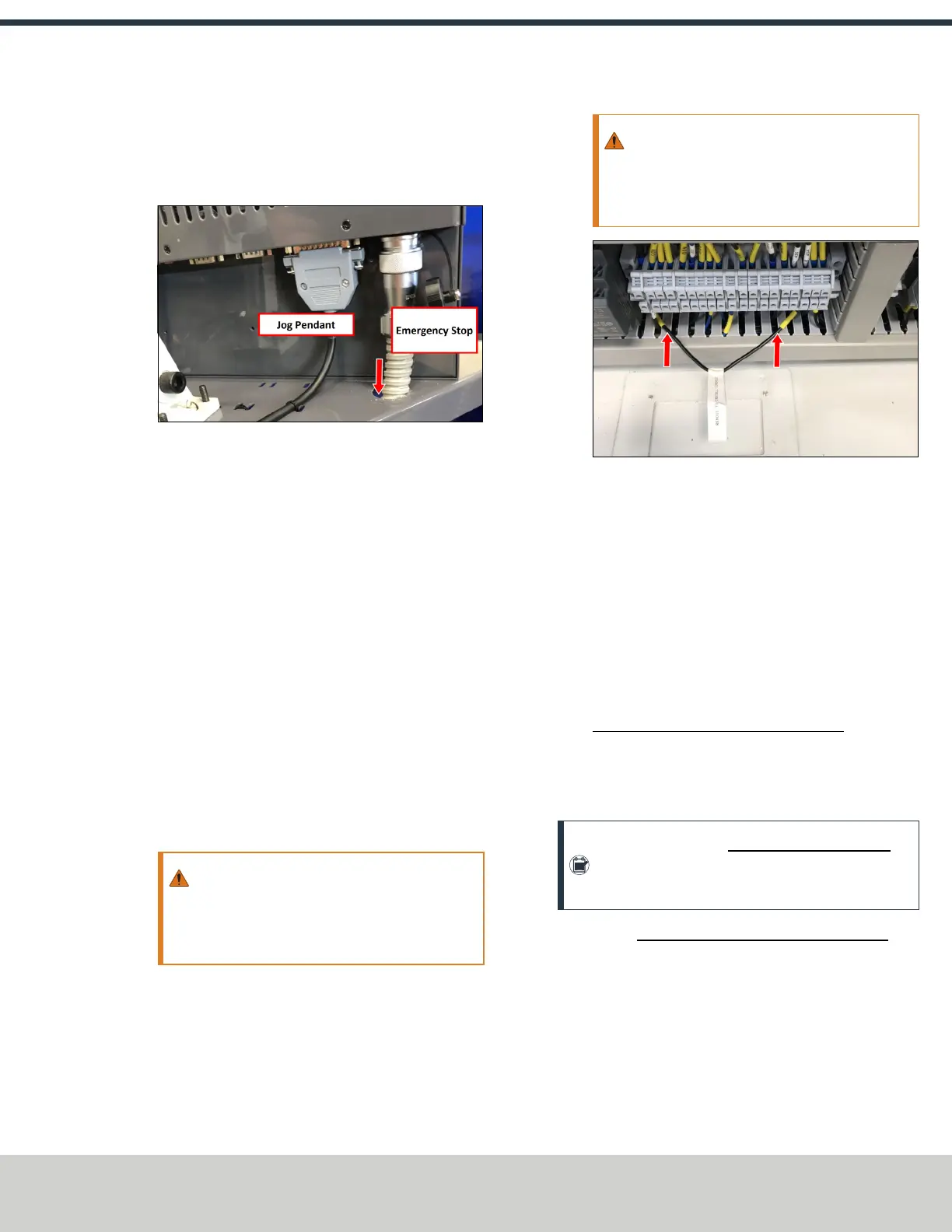
16. Open the electrical cabinet door.
17. In the electrical cabinet, identify the jumper wire labeled
Remove to Install Console, and remove it from the
machine.
WARNING! You must move the jumper from
the machine. If the jumper isn't removed, the
console's Emergency Stop button won't
function.
Figure 4-20: Jumper wire labeled Remove to Install
Console.
18. Verify that the terminals are securely screwed down
after removing the jumper wire.
19. Close the electrical cabinet door.
Install the Monitor
Tools and Items Required
l 3 mm hex wrench
l 8 mm hex wrench
l 16 mm wrench
l PathPilot Controller Vesa Mount (PN 50382)
The PathPilot controller mount allows you to install the
PathPilot controller behind the monitor (which is attached to
the Controller Arm).
Note: If you're using a Touch Screen Kit (PN35575),
you must first remove the stock mounting bracket
from the back of the monitor.
1. Put the PathPilot Controller Vesa Mount (PN 50382)
against the monitor mounting plate. Then, put the
monitor on the other side of the PathPilot controller
mount, and align the holes on the three components.
©Tormach® 2021
Specifications subject to change without notice.
Page 31 UM10753: 8L Operator's Manual (Version 0321B)
For the most recent version, see tormach.com/support