6: BASIC OPERATIONS
Touch Z
1. Jog the machine toward the part zero (usually the face
of the workpiece) in the Z direction.
2. Move the tool so that its cutting edge is just touching the
surface of the material and define this as Z = 0. Use a
sheet of paper to indicate when the tool is touching the
material.
3. Slowly jog the Z-axis until it's approximately 1/4 in.
away from part zero on the workpiece.
4. With the paper between the tool and the workpiece,
slowly jog the machine until you feel a light pull on the
paper.
5. In the Touch ZDROfield, type the thickness of the piece
of paper. Then select Touch Z.
6.9.2 About Tool Offsets
Tool offsets allow you to use various tools while still
programming with respect to the workpiece. Tools can have
different lengths (and, while using gang tooling, different X/Z
positions on the carriage).
Tool offsets are broken down into two components:
l
Geometry Offsets Represents the distance from the
work offset zero location to the tool’s control point.
Note: Unlike on a mill (where G43 must be
called out to apply an offset), tool geometry
offsets are automatically applied with the Txx
tool change command.
l
Wear Offsets
The sign convention for the machine are as follows:
l Z negative is toward the spindle.
l X negative is toward the operator.
Sign convention is important when you choose the manual tool
change option or the gang tooling option.
All tools mounted for use on the operator side of the
workpiece are touched off using negative X (diameter) values,
and most X words in part programming for these tools have
negative values.
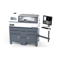
6.9.3 Import and Export the Tool Table
You can manage the tool table using an external .csv file.
Figure 6-17: Export and Import buttons on the Offsets tab.
Import a .csv File
1. Transfer the .csv file to a USB drive.
2. Insert the USB drive into the PathPilot controller.
3. Confirm that the PathPilot controller is on.
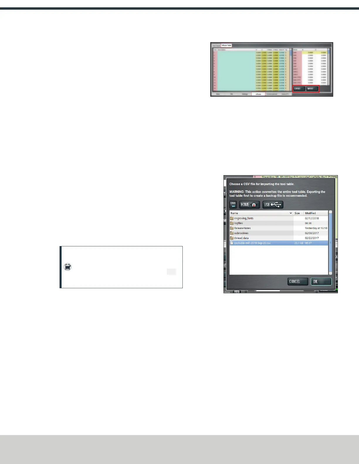
4. From the Offsets tab, on the Offsets Table tab, select
Import.
The Import dialog box displays.
Figure 6-18: Import dialog box.
5. Navigate to the .csv file on the USB drive. Then, select
OK.
The .csv file updates the tool table.
Export the Tool Table as a .csv File
1. From the Offsets tab, on the Offsets Table tab, select
Export.
PathPilot generates the .csv file, and the Export dialog
box displays.
©Tormach® 2021
Specifications subject to change without notice.
Page 51 UM10753: 8L Operator's Manual (Version 0321B)
For the most recent version, see tormach.com/support