4: INSTALLATION
8. Connect the monitor's power cord. Depending on the
type of monitor you have, do one of the following:
l
Standard LCDMonitor (PN30615)
a. Connect two of the Controller/Monitor cables
(provided in the machine owner's kit) together.
Then, connect one end of the cable assembly into
the monitor.
b. Route the loose end of the cable assembly down
the monitor post, through the square tube arm,
and toward the electrical cabinet.
c. Connect the cable assembly into one of the
Accessory Power Ports.
l
Touch Screen Kit (PN35575)
a. Connect the monitor's power supply into the
monitor.
b. Route the power supply down the monitor post.
c. Connect one end of one Controller/Monitor cable
(provided in the machine owner's kit) to the loose
end of the monitor's power supply.
d. Route the loose end of the Controller/Monitor
cable through the square tube arm and toward the
electrical cabinet.
e. Connect the loose end of the Controller/Monitor
cable into one of the Accessory Power Ports.
f. Attach the power supply to the monitor post with
one cable tie (provided in the machine owner's
kit).
9. Connect the PathPilot controller's power supply to the
PathPilot controller.
10. Connect the loose end of the power supply to one of the
Controller/Monitor cables provided.
11. Route the power cable down the monitor post, through
the square tube arm, and toward the electrical cabinet.
12. Connect the loose end of the Controller/Monitor cable
into one of the Accessory Power Ports.
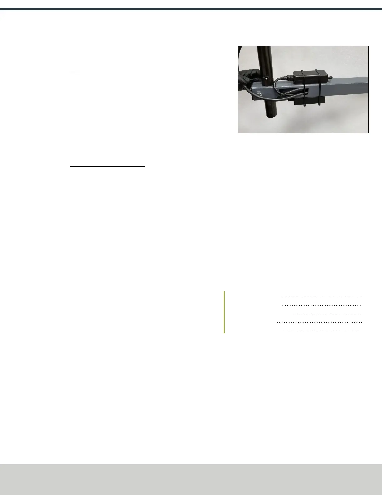
13. Attach the PathPilot controller and monitor power
supplies to the square tube arm with cable ties (provided
in the machine owner's kit).
Figure 4-25: Power supply attached to the square tube
arm.
14. Find the Ethernet cable (provided in the machine
owner's kit), and then connect it to the Controller
Communications outlet.
15. Route the loose end of the Ethernet cable toward the
PathPilot controller, and then connect it to the PathPilot
controller.
16. Secure the operator box cable, Ethernet cable, and
power supply cables to the Controller Arm with four wire
tie mounts and four cable ties that you installed on the
round monitor post in "Install the Controller Arm"
(page28).
4.6.3 Verify the Installation
After installing the base machine, you must verify the
installation. Complete the following steps in the order listed:
Power On the Machine 33
Power Off the Machine 35
Verify Limit Switch Function 35
Verify Axes Function 35
Verify Spindle Function 36
Power On the Machine
1. Use a multimeter to verify that the electrical service in
your location meets the following requirements. If your
location does not meet these requirements, do not
install the machine. Instead, you must consult with a
local electrician about your options.
l
Primary Power RequiredSingle-Phase 115 Vac,
50/60 Hz
l
Recommended Circuit AmperageDedicated 15 A
breaker
2. Connect the machine's mains power cable to the verified
electrical service.
©Tormach® 2021
Specifications subject to change without notice.
Page 33 UM10753: 8L Operator's Manual (Version 0321B)
For the most recent version, see tormach.com/support