InstallingtheRateControl
ManifoldValve
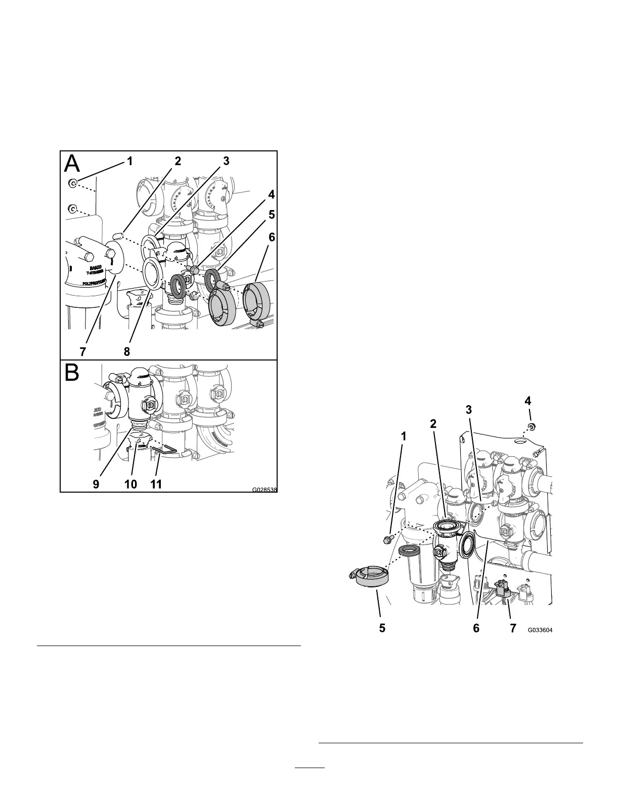
1.Alignagasketbetweentheangesoftherate
controlvalvemanifoldandthepressurelter
head(Figure123A).
Note:Ifneeded,loosenthemountinghardware
forthepressurelterheadasneededtoprovide
clearance.
g028538
Figure123
1.Locknut(1/4
inch)
5.Gasket9.Coupling
(manifold-valve)
2.Valvemount6.Flangeclamp
10.Socket(outlet
tting)
3.Flange
(agitation-valve)
7.Flange
(pressurelter
head)
11.Retainer
4.Flanged-head
bolt(1/4x3/4
inch)
8.Flange(rate
controlvalve)
2.Assembletheratecontrolvalvemanifold,
gasket,andpressurelterheadwithaange
clampandtightenbyhand(Figure123A).
3.Alignagasketbetweentheangesoftherate
controlvalveandtheagitation-valvemanifold
(Figure123A).
4.Assembletheratecontrolvalvemanifold,
gasket,andagitation-valvemanifoldwitha
angeclampandtightenbyhand(Figure123A).
5.Assembletheratecontrolvalvetothevalve
mountwiththe2anged-headboltsand2
angedlocknuts(Figure123A)thatyouremoved
instep3ofRemovingtheRateControlManifold
Valve(page77)andtorquethenutandboltto
10to12N∙m(90to110in-lb).
6.Assembletheoutletttingontothecoupling
ttingatthebottomofthemanifoldfortherate
controlvalve(Figure123B).
7.Securetheoutletttingcouplingttingby
insertingaretainerintothesocketoftheoutlet
tting(Figure123B).
8.Ifyouloosenedthemountinghardwareforthe
pressurelterhead,tightenthenutandboltto
10to12N∙m(90to110in-lb).
InstallingtheAgitationManifold
Valve
1.Aligntheangeoftheagitation-valvemanifold,
agasket,andtheangeoftheagitationbypass
valve(Figure124).
Note:Ifneeded,loosenthemountinghardware
forthemaster-boomvalveasneededtoprovide
clearance.
g033604
Figure124
1.Flanged-headbolt(1/4x
3/4inch)
5.Flangeclamp
2.Gasket
6.Valvemount
3.Manifold(agitationvalve)7.3-pinconnector(valve
actuator—agitationvalve)
4.Flangedlocknut(1/4inch)
83