RemovingtheRateControl
ManifoldValve
1.Remove2angeclampsand2gasketsthat
securethemanifoldfortheratecontrolvalve
(Figure110)tothepressurelterandagitation
valve.
Note:Retaintheangeclampsandgaskets
forinstallationinInstallingtheRateControl
ManifoldValve(page83).
g033584
Figure110
1.Flange(pressurelter
head)
4.Flangeclamp
2.Manifold(ratecontrol
valve)
5.Gasket
3.Flange(agitationvalve)6.3-pinconnector(valve
actuator—ratecontrol
valve)
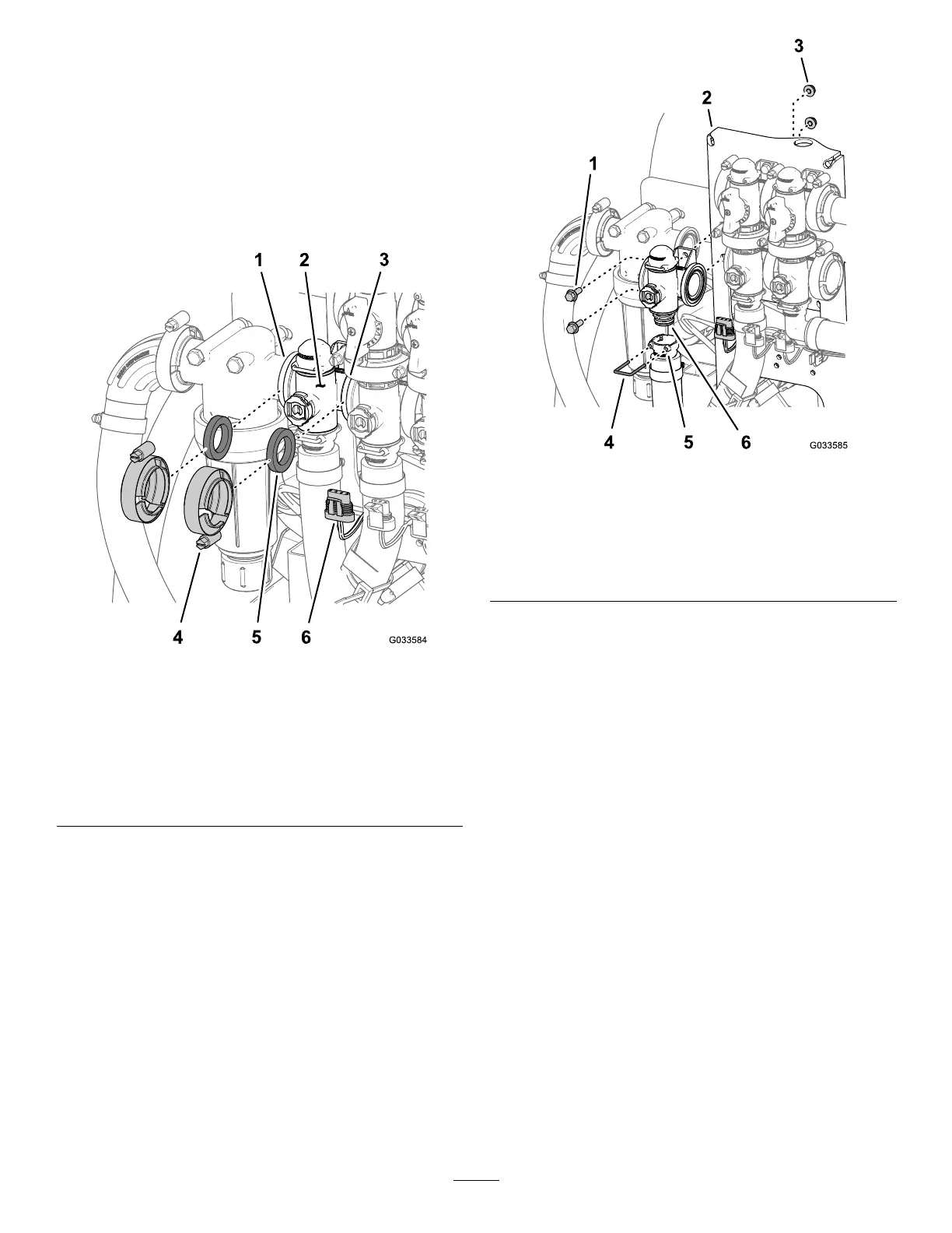
2.Removetheretainerthatsecuretheoutlettting
tothemanifoldcouplingfortheratecontrolvalve
(Figure111).
g033585
Figure111
1.Flange-headbolt(1/4x
3/4inch)
4.Retainer
2.Valvemount
5.Socket(outlettting)
3.Flangelocknut(1/4inch)6.Coupling(manifold—rate
controlvalve)
3.Removethe2ange-headbolts(1/4x3/4inch)
and2angelocknuts(1/4inch)thatsecure
theratecontrolvalvetothevalvemountand
removethevalvemanifoldfromthemachine
(Figure111).
Note:Ifnecessary,loosenthemounting
hardwareforthepressurelterheadtoease
removaloftheratecontrolvalve.
Note:Retaintheange-headbolts,ange
locknuts,andretainerforinstallationinInstalling
theRateControlManifoldValve(page83).
77