RemovingtheAgitationManifold
Valve
1.Remove3angeclampsand3gasketsthat
securethemanifoldfortheagitationvalve
(Figure112)totheagitationbypassvalve,rate
controlvalve,andmaster-boomvalve.
Note:Retaintheangeclampsandgasketsfor
installationinInstallingtheAgitationManifold
Valve(page83).
g033586
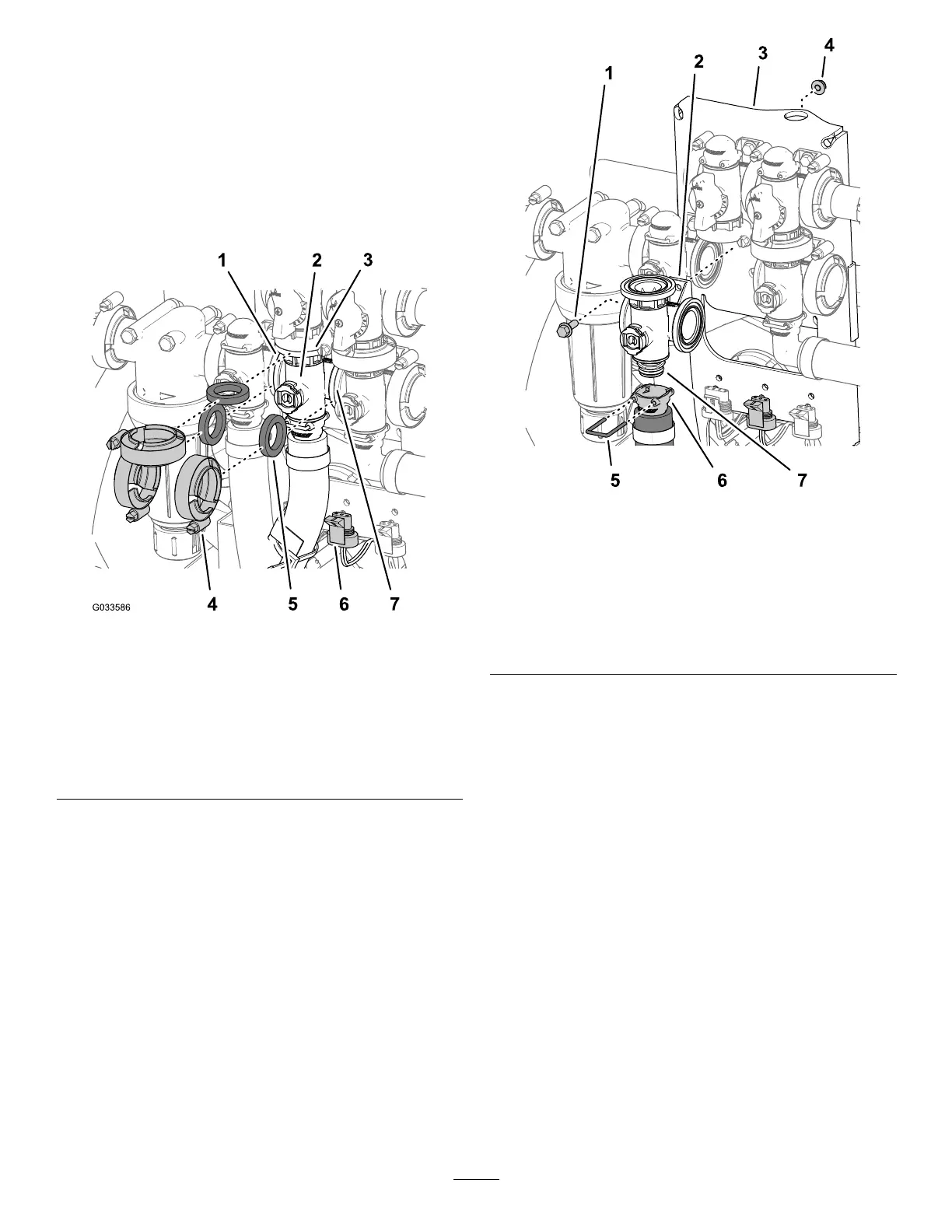
Figure112
1.Flange(pressurelter
head)
5.Gasket
2.Manifold(agitationvalve)6.3-pinconnector(valve
actuator—agitationvalve)
3.Flange(bypass
valve—agitationvalve)
7.Flange(master-boom
valve)
4.Flangeclamp
2.Removetheretainerthatsecurethe
quick-disconnectsockettothemanifold
quick-disconnectcouplingfortheagitationvalve
(Figure113).
g214596
Figure113
1.Flange-headbolt(1/4x
3/4inch)
5.Retainer
2.Manifoldvalve(agitation
valve)
6.Quick-disconnecttting
(socket)
3.Valvemount
7.Quick-disconnecttting
(coupling)
4.Flangelocknut(1/4inch)
3.Removetheange-headbolt(1/4x3/4inch)and
angelocknut(1/4inch)thatsecuretheagitation
valvetothevalvemountandremovethevalve
manifoldfromthemachine(Figure113).
Note:Retaintheangeheadbolt,ange
locknut,andretainerforinstallationinInstalling
theAgitationManifoldValve(page83).
78