g033591
Figure127
1.Manifold(master-boom
valve)
4.Flanged-headbolt(1/4x
3/4inch)
2.Valvemount5.Retainer
3.Flangedlocknut(1/4inch)6.Socket(90°outlettting)
6.Securetheoutletttingcouplingttingby
insertingaretainerintothesocketoftheoutlet
tting(Figure127).
7.Assembletheagitationvalvetothevalvemount
withtheanged-headboltandangedlocknut
(Figure126)thatyouremovedinstep3of
RemovingtheMasterBoomManifoldValve
(page79)andtorquethenutandboltto10to12
N∙m(90to110in-lb).
InstallingtheSectionManifold
Valve
1.Inserttheupperend-capttingofthemanifold
valveintothebypasstting(Figure128A).
Note:Ifneeded,loosenthemountinghardware
forthebypassttingtoprovideclearance.
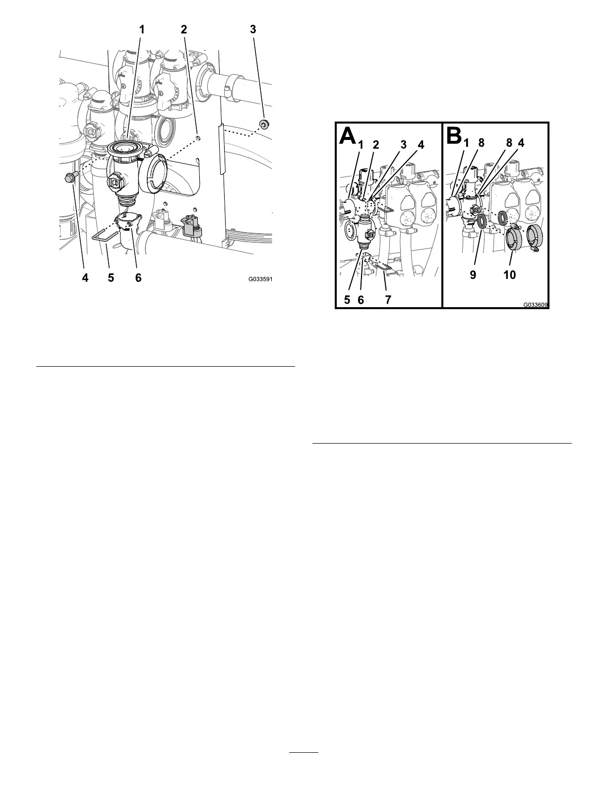
g033609
Figure128
1.Flange(reducercoupling)6.Socket(outlettting)
2.Socket(bypasstting)
7.Retainer
3.Bypasstting8.Flange(manifold—section
valve)
4.Flange(adjacent
manifold—agitationvalve)
9.Gasket
5.End-captting(manifold
valveassembly)
10.Flangeclamp
2.Securetheend-capttingtothebypasstting
byinsertingaretainerintothesocketofthe
bypasstting(Figure128A).
3.Assembletheoutletttingontothelower
end-capttingofthemanifoldvalve(Figure
128A).
4.Securetheend-capttingtotheoutletttingby
insertingaretainerintothesocketoftheoutlet
tting(Figure128A).
5.Alignagasketbetweentheangesofthe
reducercouplingandthesectionvalvemanifold
(Figure128B).
6.Assemblethereducercoupling,gasket,and
sectionvalvemanifoldwithaclampandtighten
byhand(Figure128B).
7.Ifinstallingthe2leftmostsectionvalves,align
agasketbetweentheangesofthe2adjacent
sectionvalvemanifolds(Figure128B).
8.Assemblethe2adjacentsectionvalvemanifolds
andgasketwithaclampandtightenbyhand
(Figure128B).
85