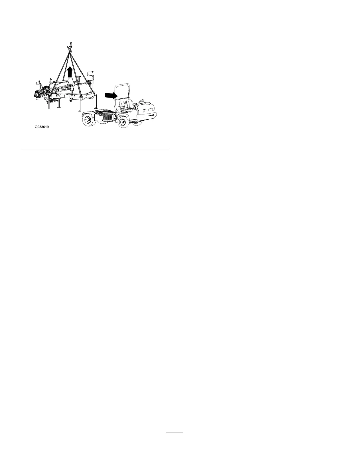
RemovingtheSprayerSkid
1.Lowertheboomstoapproximately45°andthen
pivotthemforward(Figure132).
g033619
Figure132
2.Removethe2bolts(1/2x1-1/2inches)and
2locknuts(1/2inch)thatsecurethehold
downbracketofthetankskidassemblytothe
bedbracketontheframeateachsideofthe
machine;referto13LoweringtheTankSkid
(page30).
3.Raisethetankskidwiththeliftcylinders,install
thecylinderlock,andperformthefollowing:
Note:RefertoRaisingtheTankAssembly
(page69).
•ForHD-andHDX-SeriesWorkmanmodels
withamanualtransmission,disconnectthe
PTOshaftfromthetransaxlePTO;refer
totheinstallationinstructionsfortheMulti
ProWMTurfSprayerFinishingKit,Manual
WorkmanUtilityVehicle.
•ForHDXWorkmanwithaautomatic
transmission,disconnectthehosesatthe
high-owhydraulicpanelandcapthettings;
refertotheinstallationinstructionsforthe
MultiProWMTurfSprayerFinishingKit,
AutomaticWorkmanUtilityVehicle.
•Disconnectthespeedsensorwiring;
refertoConnectingtheSpeedSensor
Harness(HD-SeriesModelswithaManual
Transmission)(page22)andConnectingthe
SpeedSensorHarness(HDX-AutoModel)
(page22).
4.Removethecylinderlockandlowerthetank
skidwiththeliftcylinders;refertoLoweringthe
TankAssembly(page70).
5.Attachtheliftingequipmenttothehorizontal
tubesoftheforwardjackstandsandthevertical
postoftherearjackstands(Figure132).
6.Liftthetankassembly7.5to10cm(3to4
inches),andremovethelynchpinsandclevis
pinssecuringtheliftcylinderstothetank
assembly.
7.Liftthetankskidfromthemachinehighenough
tocleartheskidfromthemachine(Figure132).
8.Carefullymovethevehicleforwardandaway
fromthetankskid.
9.Slowlylowertheskidtanktotheground.
89