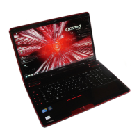
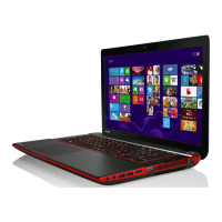
4 Replacement Procedures
QOSMIO F20 Maintenance Manual (960-526) [CONFIDENTIAL] 4-v
Figures
Figure 4-1 Removing the battery pack.................................................................................4-8
Figure 4-2 Removing the PC card .....................................................................................4-10
Figure 4-3 Removing the bridge media .............................................................................4-11
Figure 4-4 Removing the HDD slot cover..........................................................................4-12
Figure 4-5 Removing the HDD assembly...........................................................................4-13
Figure 4-6 Removing the HDD...........................................................................................4-13
Figure 4-7 Removing the memory module........................................................................4-15
Figure 4-8 Removing the MDC ..........................................................................................4-17
Figure 4-9 Removing the speaker cover .............................................................................4-18
Figure 4-10 Removing the keyboard ...................................................................................4-19
Figure 4-11 Removing the keyboard support plate..............................................................4-20
Figure 4-12 Removing the switch membrane ......................................................................4-22
Figure 4-13 Removing the screws (bottom) ........................................................................4-23
Figure 4-14 Removing the cables (bottom) .........................................................................4-24
Figure 4-15 Removing the insulators and glass tape ...........................................................4-24
Figure 4-16 Removing the screws and cables......................................................................4-25
Figure 4-17 Removing the display assembly.......................................................................4-26
Figure 4-18 Removing the wireless LAN antenna ..............................................................4-27
Figure 4-19 Removing the display.......................................................................................4-28
Figure 4-20 Removing the wireless LAN card ....................................................................4-31
Figure 4-21 Removing the RTC battery..............................................................................4-32
Figure 4-22 Removing the UA board ..................................................................................4-33
Figure 4-23 Passing the cable ..............................................................................................4-34
Figure 4-24 Removing the optical drive assembly ..............................................................4-35
Figure 4-25 Disassembling the side bracket........................................................................4-36
Figure 4-26 Removing the fan.............................................................................................4-37
Figure 4-27 Removing the Modem jack ..............................................................................4-38
Figure 4-28 Removing the system board .............................................................................4-39
Figure 4-29 Removing DC-IN jack and LAN jack..............................................................4-40
Figure 4-30 Passing of the cables ........................................................................................4-41
Figure 4-31 Removing the TV tuner module.......................................................................4-42
 Loading...