,-
,-,,-,
I
I,-
•
,-,
I I (AM/FM Adjustment Parameters)
-
,-
,-,,-'
,-
I I
=11_
,-,,-,,-,
1-11 I
=11_
Meter
adjustment
parameters
1
1-
,-,
.•
- I I
,
,,-,,-,
1-11 I
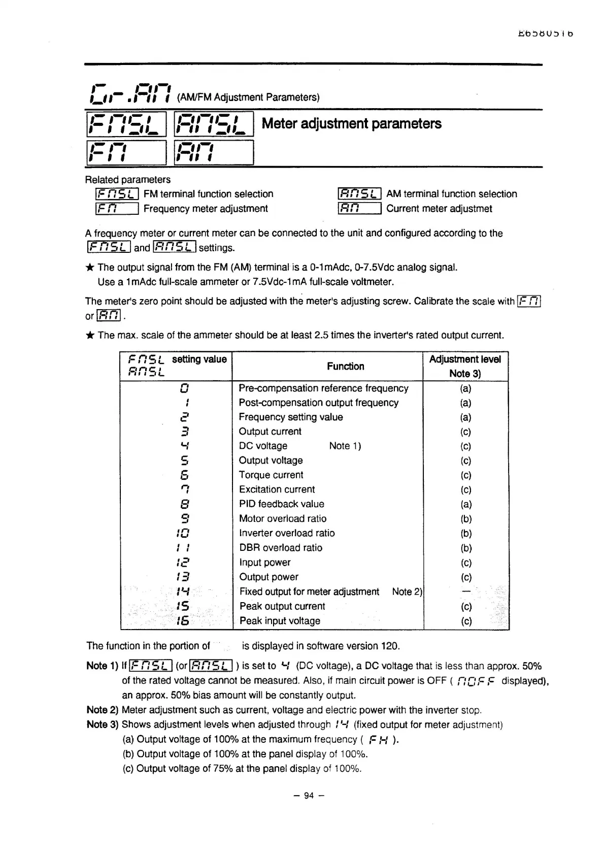
Related parameters
IF
n s L I FM terminal function selection
IF
n I Frequency meter adjustment
1.c:
n s L I AM terminal function selection
IR
n I Current meter adjustmet
A frequency meter or current meter can be connected to the unit and configured according to the
IF
nsL
I and
IRnSL
I settings.
*The
output signal from the FM (AM) terminal is a 0-1mAdc,0-7.5Vdc analog signal.
Use a 1 mAdc full-scale ammeter or 7.5Vdc-1 mA full-scale voltmeter.
The meter's zero point should be adjusted with the meter's adjusting screw. Calibrate the scale with
It=
n I
orlRnl.
* The max. scale of the ammeter should be at least 2.5 times the inverter's rated output current.
FrtSL
setting value
Function
Adjustment level
Rn
SL
Note
3)
n
Pre-compensation reference frequency
(a)
u
'
Post-compensation output frequency
(a)
'
2
Frequency setting value
(a)
3
Output current
(c)
.....
I
DC voltage Note
1)
(C)
s
Output voltage
(c)
6
Torque current
(c)
r1
Excitation current
(C)
I
8
PIO
feedback value
(a)
9
Motor overload ratio
(b)
1r1
Inverter overload ratio
(b)
•u
I
I
DBR overload ratio
(b)
'
I
:2
Input power
(C)
13
Output power
(c)
"-'
·I I ,
Fixed output for meter adjustment Note2)
-
>-
..
-
..
JS
Peak output current
(c)
.,.
>15·
··
·
··.·
.
Peak input voltage
(c)
The function
in
the portion of is displayed
in
software version 120.
Note
1)
It
IF
nsL
I
(orlRnSL
I)
is set to
4-f
(DC voltage), a
DC
voltage that
is
less than approx. 50%
of the rated voltage cannot
be
measured. Also, if main circuit power is OFF ( n
C:
,c
,c
displayed),
an approx. 50% bias amount will be constantly output.
Note 2) Meter adjustment such as current,
voltage and electric power with the inverter stop.
Note
3)
Shows adjustment levels when adjusted through I '-I (fixed output for meter adjustment)
(a)
Output voltage of 100% at the maximum frequency ( F
f-f
).
(b)
Output voltage of 100% at the panel display of 100%.
(c)
Output voltage of 75% at the panel display of 100%.
- 94 -

 Loading...


