E6580516
,-
,-
,_,,-
..
-
(Fundamental Parameters #1)
,-,-
=··-
,_,
I
I
Related parameters
,-
1-
I I
-,,
,-,
- -
IS
[ w I I Ace/Dec pattern
#1
IS
[ L I Ace/Dec pattern adjustment
(LOW)
Ace/Dec
patterns,
Ace/Dec
pattern
adjustment,
Low/High
IS
[
1-1
I Ace/Dec pattern adjustment (HIGH)
An ace/dee pattern that matches the application can be selected.
S [ w I set to 0 (Linear ace/dee) This is a general acceleration/deceleration pattern, and
is used under
most
circumstances.
S [
'-'
I set to : (Self- adjusting function) An acceleration/decleration time that matches the load
conditions is automatically set.
Self-adjusting function
This fuction cannot be used when the frequency reference constantly fluctuates
or
when the load
changes suddenly.
The
IF/[
[
:I
ldE
[
II
parameters will
be
automatically changed, but when the
control power is turned OFF, the settings will return
to
their original values.
To save the self-adjusting function results, display
IRC
[
:I
ldE
[
:I
in
[,,-.Lf,
pressl
ENTER!,
make the data setting blink by pressing the
~
or@)
keys once, and then press I ENTER I again
to
write the data.
Set
[,,-
.F
c'
ISC
1..1c
1
lfor
IRC
c
21
and
lc:E
c
c'I.
S [
,_,
I set to 2 ($-Pattern #1) This pattern is used when accelerating/decelerating to a
high speed
area
(exceeding 60Hz) is required in a short
S [
'-'
I set to 3 (S-Pattern #2)
time.
This
pattern is suitable for conveyers, etc.
This pattern
gradually accelerates in the field-weakening
area where the motor's acceleration torque is small. This
pattern is
suitable for high-speed spindles.
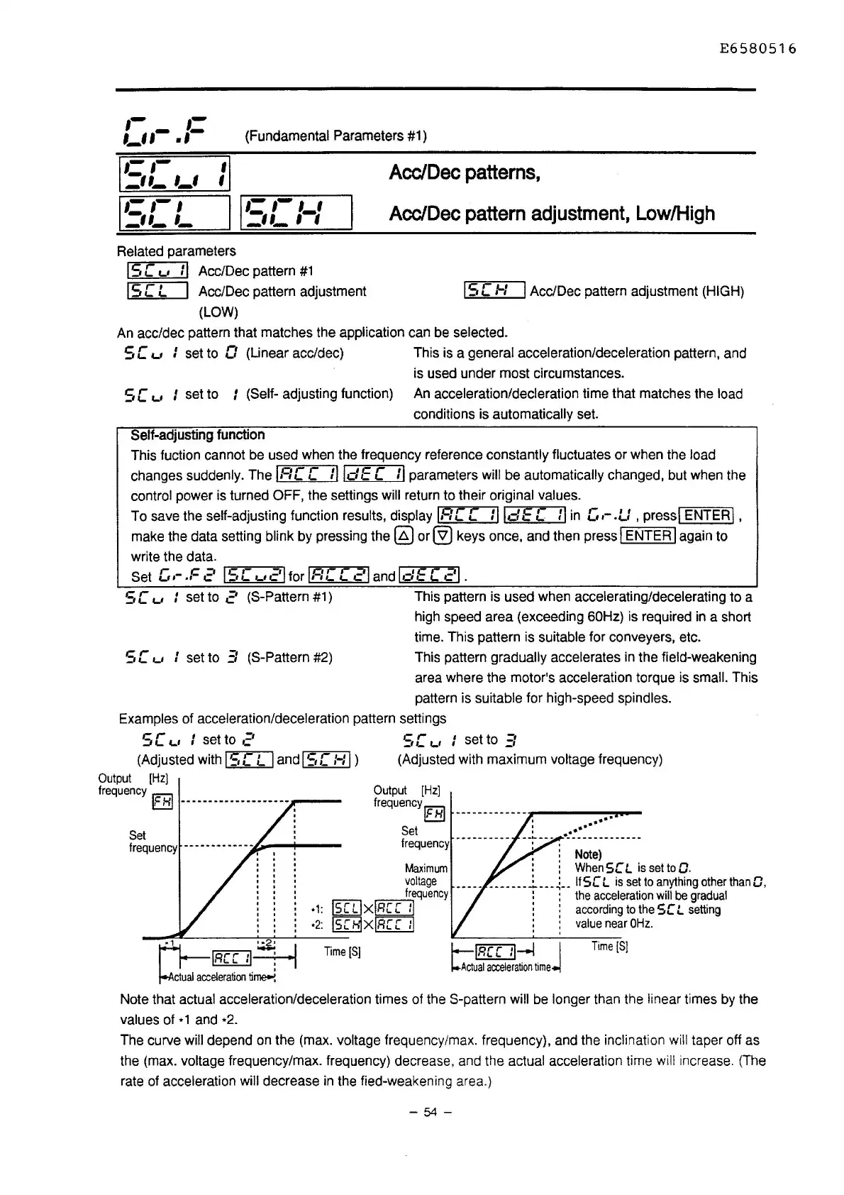
Examples
of acceleration/deceleration pattern settings
5 [
'-'
I set to
c'
(Adjusted with
IS
[ L I and
IS
[:-:I )
Output
(Hz]
frequency
IEE!
-----------------------
Set
frequency
-------------..1.-
;..----4---
SC'-' : set to
Et
(Adjusted with maximum voltage frequency)
Output
[Hz]
frequency
IEE!
-------------
I
••••
Set
:
••••••
frequency
·---------
··:·--.
--------------
• :
Note)
Maximum
: :
When
SC
L
is
set
to
O.
voltage
____________
j__
__
~--
lfSC
L
is
set
to
anything
other
than
0,
frequency
: :
the
acceleration
will
be
gradual
•1:
lSCLixlRCC
11
: accordingtotheSCL
setting
. ,
~,..,..,~I
~-n
cceleration
ti~
·2:
ISC61XIRC
C
11
:
value
near
OHz
.
Time[S]
Time[S]
l--lfl£Lll-l j
~Actual
acceleration
time
Note that actual acceleration/deceleration times of the S-pattern will be longer than the linear times by the
values of * 1 and *2.
The curve
will depend on the (max. voltage frequency/max. frequency), and the inclination will taper off as
the (max. voltage frequency/max. frequency) decrease, and the actual acceleration time will increase. (The
rate of acceleration will decrease in the tied-weakening area.)
- 54 -

 Loading...


