E6580516
62
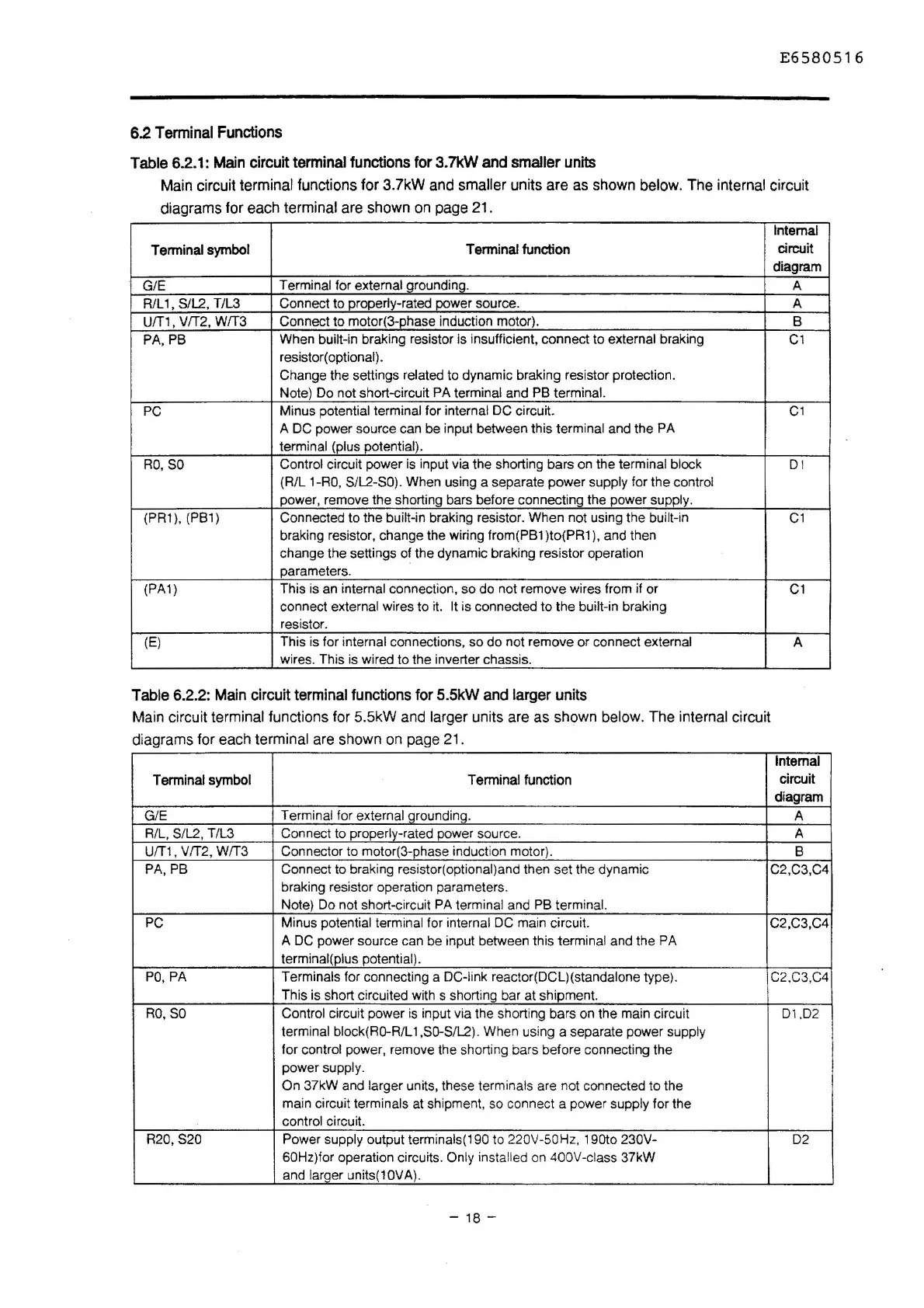
Terminal Functions
Table 6.2.1:
Main
circuit terminal functions for
3.7k.W
and
smaller units
Main circuit terminal functions for 3.7kW and smaller units are as shown below. The internal circuit
diagrams for each terminal are shown
on
page 21.
Internal
Terminal symbol
Terminal function
circuit
diagram
G/E
Terminal for external grounding.
A
R/L 1,
S/L2, T/L3
Connect to properly-rated power source.
A
U/T1, V/T2, W/T3
Connect to motor(3-phase induction motor).
B
PA,PB
When built-in braking resistor is insufficient, connect
to
external braking
C1
resistor( optional).
Change the settings related to dynamic braking resistor protection.
Note) Do not short-circuit
PA terminal and PB terminal.
PC
Minus potential terminal for internal DC circuit.
C1
A DC power source can be input between this terminal and the PA
terminal (plus potential).
RO
,
SO
Control circuit power is input via the shorting bars on the terminal block
D I
(R/L
1-RO
, S/L2-SO). When using a separate
power
supply for the control
power, remove the shorting bars before connecting the power supply.
(PR1
),
(PB1)
Connected to the
built-in braking resistor.
When
not using the built-in
C1
braking resistor, change the wiring from(PB1 )to(PR1
),
and then
change the settings of the dynamic braking resistor operation
parameters.
(PA1)
This is an
internal connection,
so
do
not remove wires from if or
C1
connect external wires
to
it. It is connected to the built-in braking
resistor.
(E)
This is for internal connections,
so
do
not remove or connect external
A
wires. This is wired to the inverter chassis.
Table
6.2.2:
Main
circuit terminal functions
for
5.SkW
and
larger units
Main circuit terminal functions for 5.5kW and larger units are as shown below. The internal circuit
diagrams for each
terminal are shown
on
page
21
.
Internal
Terminal symbol
Terminal function
circuit
diagram
G/E
Terminal for external qrounding.
A
R/L,
S/L2, T/L3
Connect to
properly-rated power source.
A
U/T1, V/T2, W/T3 Connector to motor(3-phase induction motor).
B
PA. PB
Connect to braking resistor(optional)and then set the dynamic
C2,C3,C4
braking resistor operation parameters.
Note) Do not short-circuit
PA terminal and PB terminal.
PC
Minus potential terminal for internal DC main circuit.
C2,C3,C4
A DC power source can be input between this
terminal and the PA
terminal(plus
potential).
PO,
PA Terminals for connecting a DC-link reactor(DCL)(standalone type).
C2,C3,C4
This is short circuited with s shorting bar at shipment.
RO,SO Control circuit power
is
input via the shorting bars on the main circuit
D1
.D2
terminal block(RO-R/L 1,SO-S/L2). When using a separate power supply
for control power, remove the shorting bars before connecting the
power
supply.
On
37kW and larger units, these terminals are not connected to the
main circuit
terminals at shipment, so connect a power supply for the
control circuit.
R20,S20
Power supply output terminals(190 to 220V-50Hz, 190to
230V-
02
60Hz)for operation circuits. Only inst
al
led on 400V-class 37kW
and
larqer units(10VA).
- 18 -
I
I
I

 Loading...


