E6580516
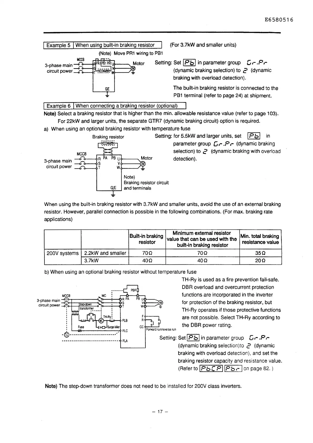
I Example 5 I When using built-in braking resistor
(For 3.7kW and smaller units)
3-phase
main
-0:
circuit
power:::~
(Note)
Move
PR1
wiring
to
PB1
Setting: Set
IP
b I
in
parameter group
[,
,-
.,o ,-
(dynamic braking selection) to 2 (dynamic
braking with
overload detection).
The
built-in braking resistor is connected to the
PB1
terminal (refer to page 24) at shipment.
I Example 6 I When connecting a braking resistor (optional)
Note) Select a braking resistor that is higher than the min. allowable resistance value (refer to page 103).
For 22kW and
larger units, the separate GTR7 (dynamic braking circuit) option is required.
a)
When using an optional braking resistor with temperature fuse
3-phase
main
--o:
. .
--0
c1rcu1t
power
__.,~
Braking
resistor Setting: for 5.5kW and larger units, set
IP
b I
in
R
PA
PB
uo---~
Motor
S
V~--{IMJ
T
Wo---~
Note)
Braking
resistor
circuit
GIE
and
terminals
'----<>-~
parameter group G
,-
.P
,- (dynamic braking
selection) to 2 (dynamic braking with overload
detection).
When using the
built-in braking resistor with 3.7kW and smaller units, avoid the use of an external braking
resistor. However,
parallel connection is possible in the following combinations. (For max. braking rate
applications)
Built-in
braking
Minimum external resistor
Min. total braking
value that can be used with the
resistor
built-in braking resistor
resistance value
200V systems
2.2kW and
smaller
700 700
350
3.7kW
400 400
200
b)
When using an optional braking resistor without temperature fuse
MCCB
MC
3-phase
main
-O.:::<>-r---~20--~-0R
PA
PB
u.,..-~---
circuit power
~--:-
~
~.....__~..,..
TH-Ry
is
used as a fire prevention fail-safe.
DBR
overload and overcurrent protection
functions are incorporated
in
the inverter
for protection of the braking resistor, but
TH-Ry operates if those protective functions
are not
possible. Select TH-Ry according to
the DBR power rating.
Surge
killer
·®·--······--------------··
FLC
----------------
-
--------
--
-
FlA
F
R
I
CC
Forward
runlreveroe
run
Setting: Set IP b I in parameter group G
,-
.P
,-
(dynamic braking selection)to
c'
(dynamic
braking with
overload detection), and set the
braking resistor capacity and resistance
value.
(Refer to
IPbC
PllPb,-
Ion
page 82. )
Note) The step-down transformer does not need to be
installed for 200V class inverters.
-
17
-

 Loading...


