,-
,-
,-
'-'
,-
.
=•
,-
(Frequency Setting Parameters)
1
1
-
,-
/
1-
1
I
Frequency
setting
input
signal
characteristics
Related parameters
Ii-
,-
/,-,I
RR
input selection
IP I
RR
reference point
#1
IP 2 RR reference point #2
IF
- P
ti
Point
#1
output frequency
IF
-
pc'
I Point #2 output frequency
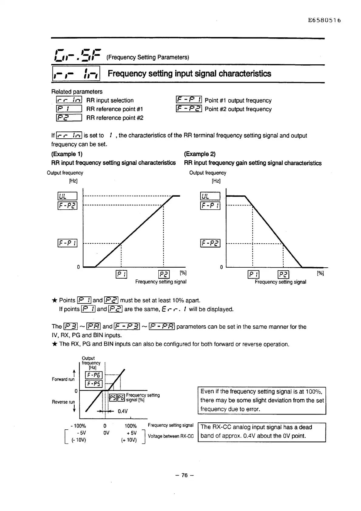
If
I,-
,-
t
,-,
I is set to I , the characteristics of the
RR
terminal frequency setting signal and output
frequency can be set.
(Example
1)
(Example 2)
E6580516
RR input frequency setting signal characteristics
Output
frequency
RR
input frequency gain setting signal characteristics
Output
frequency
[Hz]
luL
IF-P21
IF-P
:I
[£]]
IP21
[%]
Frequency
setting
signal
*Points
IP
ti
and
IPc'I
must be set at least 10% apart.
[Hz]
IUL
IF-P
:I
IF-P21
IP
:I
IP21
[%]
Frequency
setting
signal
If points
IP
II
and
IPc'I
are the same, E ,-
,-
. I will be displayed.
The
IF'
31-IF'RI and
IF
-
F'
Ell
-
IP
- PRI parameters can
be
set
in
the same manner for the
IV, RX,
PG
and BIN inputs.
*The
RX,
PG
and BIN inputs can also be configured for both forward or reverse operation.
t
Forward
run
Output
frequency
;
[Hzl
l
I F-P5 j
l----···--··
r7-"0c1
~-····
l
~::;
Ql------,~<....i...-'-------
~ ~
[IMls
~
5
F_requency
setting
l l
~~[.£1
signal
(%]
Reverse
run
~
-t-
0.4V
-100%
0
av
100%
Frequency
setting
signal
[
-5V
(-10V)
+5V J
(+
10V)
Voltage
between
RX-CC
- 76 -
Even if the frequency setting signal is at 100%,
there may be some slight deviation from the set
frequency due to error.
The RX-CC
analog input signal has a dead
band of approx.
0.4V about the
OV
point.

 Loading...


