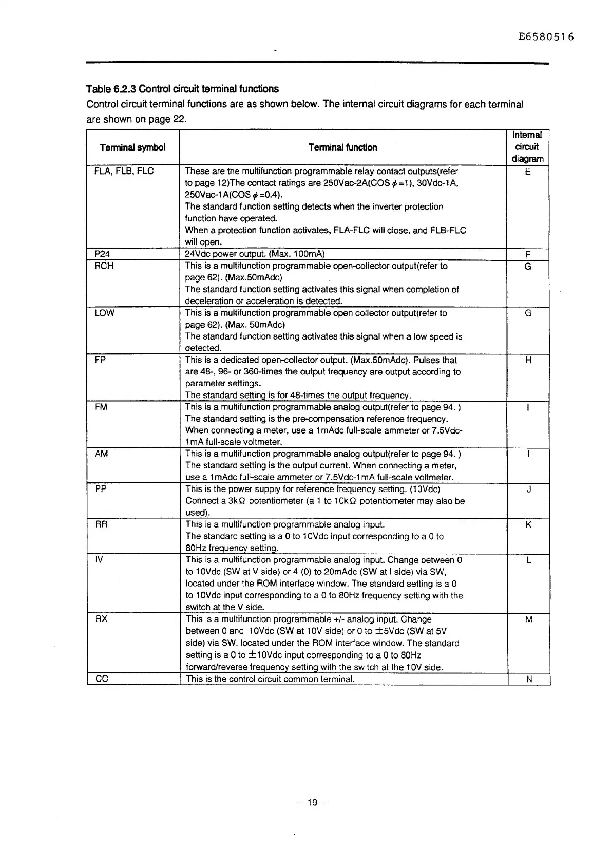
E6580516
Table
6.2.3
Control
circuit
terminal
functions
Control
circuit terminal functions
are
as
shown
below. The internal circuit diagrams for
each
terminal
are
shown
on
page
22.
Internal
Terminal
symbol
Terminal function
circuit
diagram
FLA,FLB,FLC
These are the multifunction programmable relay contact outputs(refer
E
to page 12)The contact ratings are 250Vac-2A(COS + = 1 ), 30Vdc-1
A,
250Vac-1A(COS ¢ =0.4).
The standard function setting detects when the inverter protection
function have operated.
When a protection function activates, FLA-FLC
will close, and FLB-FLC
will open.
P24
24Vdc power output. (Max. 1
OOmA)
F
RCH This is a multifunction
programmable open-collector output(refer to
G
page 62). (Max.50mAdc)
The standard function setting activates this
signal when completion of
deceleration or acceleration is detected.
LOW
This is a multifunction programmable open collector output( refer to
G
page 62). (Max. 50mAdc)
The standard function setting activates this signal when a low speed is
detected.
FP This is a dedicated
open-collector output. (Max.50mAdc). Pulses that
H
are 48-, 96-
or
360-times the output frequency are output according to
parameter settings.
The standard setting is for 48-times the output frequency.
FM
This is a multifunction programmable analog output(refer to page 94. )
I
The standard setting is the pre-compensation reference frequency.
When connecting a meter, use a 1 mAdc
full-scale ammeter or 7 .5Vdc-
1 mA
full-scale voltmeter.
AM This is a multifunction programmable analog output(refer to page 94. )
I
The standard setting is the output current. When connecting a meter,
use a 1 mAdc
full-scale ammeter or 7.5Vdc-1 mA full-scale voltmeter.
pp
This is the power supply for reference frequency setting.
(1
OVdc)
J
Connect a 3k Q potentiometer (a 1 to 1
Ok
Q potentiometer may also be
used).
RR This is a multifunction
programmable analog input.
K
The standard setting is a 0 to 1 OVdc input corresponding to a O to
BOHz
frequency setting.
IV
This is a multifunction programmable analog input. Change between O
L
to 1
OVdc
(SW at V side) or 4 (0) to 20mAdc (SW at I side) via SW,
located
under the ROM interface window. The standard setting is a O
to 1
OVdc
input corresponding to a 0 to 80Hz frequency setting with the
switch at the V side.
RX This is a multifunction
programmable +/- analog input. Change
M
between 0 and 1
OVdc
(SW
at
1
OV
side) or O to
±5Vdc
(SW at
5V
side) via SW, located under the ROM interface window. The standard
setting is a
0 to ± 1
OVdc
input corresponding to a Oto 80Hz
forward/reverse frequency setting with the switch at the 1
OV
side.
cc
This is the control circuit common terminal.
N
- 19 -

 Loading...


