E6580516
Internal
Terminal
symbol
Terminal
function
circuit
diagram
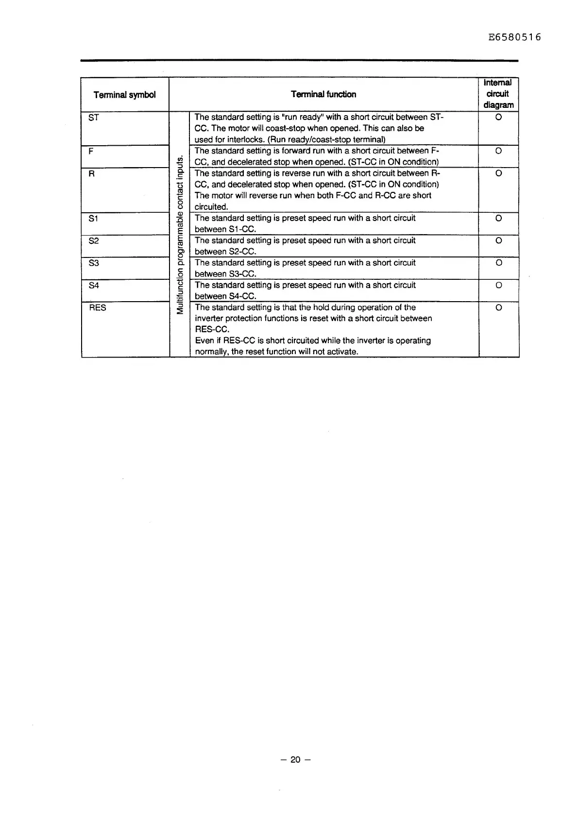
ST
The standard setting is "run ready" with a short circuit between ST-
0
CC.
The
motor will coast-stop when opened. This can also
be
used for interlocks. (Run ready/coast-stop terminal)
F
The standard setting is forward run with a short circuit between F-
0
in
CC, and decelerated stop when opened. (ST-CC
in
ON condition)
'5
R
Cl.
The standard setting is reverse run with a short circuit between R-
0
.!:
0
CC, and decelerated stop when opened. (ST-CC
in
ON condition)
.$
The motor will reverse run when both F-CC and R-CC are short
c:
0
circuited.
(.)
S1
(!)
The standard setting is preset speed run with a short circuit
0
::c
ctl
between S1-CC.
E
S2
E
The standard setting is preset speed run with a short circuit
0
~
Ol
between S2-CC.
a
S3
0..
The standard setting is preset speed run with a short circuit
0
c:
between S3-CC. a
S4
~
The
standard setting is preset speed run with a short circuit
0
c:
~
between 84-CC.
RES
:;
The standard setting is that the hold during operation of the
0
::E
inverter protection functions is reset with a short circuit between
RES-CC.
Even if RES-CC is short circuited while the inverter is operating
normally, the reset function will not activate.
-
20
-

 Loading...


