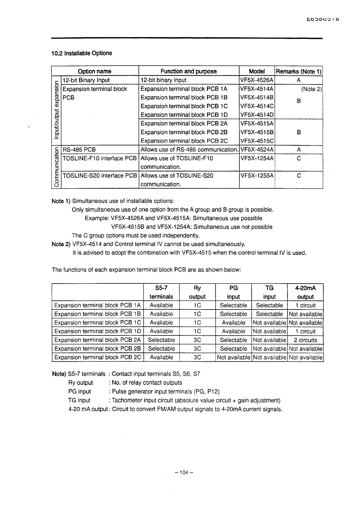
10.2 Installable Options
Option name
Function and purpose
Model
Remarks (Note 1)
c
12-bit Binary Input
12-bit binary input VF5X-4526A
0
Expansion terminal block
Expansion terminal block PCB 1 A VF5X-4514A
"iii
c
~
PCB
Expansion terminal block PCB 1 B
VF5X-45148
a.
x
Q)
Expansion terminal block PCB 1 C
VF5X-4514C
:5
Expansion terminal block PCB 1 D VF5X-4514D
a.
:5
Expansion terminal block PCB 2A VF5X-4515A
0
~
::l
Expansion terminal block PCB 2B
VF5X-45158
a.
E
Expansion terminal block PCB 2C VF5X-4515C
c
RS-485 PCB Allows use of RS-485 communication.
VF5X-4524A
0
~
TOSLINE-F10 interface PCB
Allows use
ofTOSLINE-F10 VF5X-1254A
(.)
·c:
communication.
::l
E
TOSLINE-S20 interface PCB Allows use of TOSLINE-S20 VF5X-1255A
E
0
communication.
()
Note 1) Simultaneous use of installable options:
Only simultaneous use of one option from the A group and 8 group is possible.
Example: VF5X-4526A and VF5X-4515A:
Simultaneous use possible
VF5X-4515B and VF5X-1254A:
Simultaneous use not possible
The C group options must be used independently.
Note 2) VF5X-4514 and Control terminal
IV
cannot be used simultaneously.
A
(Note
2)
B
8
A
c
c
It
is
advised to adopt the combination with VF5X-4515 when the control terminal IV is used.
The functions of each expansion
terminal block PCB are as shown below:
55-7 Ry
PG
TG
terminals output
input input
Expansion
terminal block PCB 1 A Available 1C
Selectable Selectable
Expansion
terminal block PCB 1 B Available
1C Selectable Selectable
Expansion terminal block PCB 1 C Available
1C Available Not available
Expansion terminal block PCB 1 D Available
1C Available Not available
Expansion terminal block PCB 2A
Selectable
3C
Selectable Not
available
Expansion terminal block PCB 2B Selectable
3C Selectable Not available
Expansion terminal block PCB 2C Available
3C
Not available Not
available
Note) S5-7 terminals : Contact input terminals
SS,
S6, S7
Ry
output : No. of relay contact outputs
:
Pulse generator input terminals (PG, P12)
PG
input
TG input
: Tachometer input circuit (absolute
value
circuit+
gain adjustment)
4-20 mA output: Circuit to convert FM/AM output signals to 4-20mA current signals.
-104-
4-20mA
output
1 circuit
Not
available
Not available
1 circuit
2 circuits
Not available
Not
available

 Loading...


