Braking during power off:
Loads that generate a
negative torque:
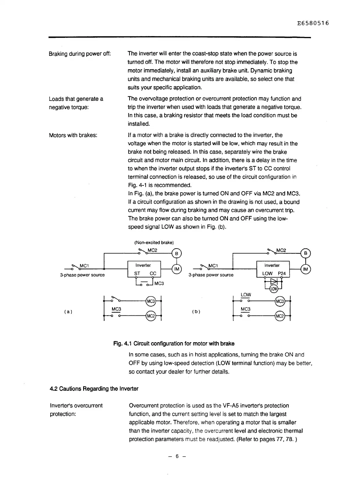
Motors with brakes:
3-phase power source
(a)
E6580516
The inverter will enter the coast-stop state when the power source is
turned off. The motor
will therefore not stop immediately.
To
stop the
motor
immediately, install an auxiliary brake unit. Dynamic braking
units and mechanical braking units are
available, so select one that
suits your specific
application.
The overvoltage protection
or
overcurrent protection may function and
trip the inverter when used with
loads that generate a negative torque.
In this case, a braking resistor that meets the load condition must be
installed.
If
a motor with a brake is directly connected to the inverter, the
voltage when the motor is started
will be low, which may result
in
the
brake not being
released. In this case, separately wire the brake
circuit and motor main circuit.
In
addition, there is a delay
in
the time
to when the inverter output stops if the inverter's
ST to CC control
terminal
connection is released, so use of the circuit configuration
in
Fig.
4-1
is recommended.
In
Fig. (a), the brake power is turned ON and OFF via MC2 and MC3.
If a circuit configuration as shown
in
the drawing is not used, a bound
current may
flow during braking and may cause an overcurrent trip.
The brake power can
also be turned ON and OFF using the low-
speed signal LOW as shown
in
Fig. (b).
(Non-excited brake)
MC2
MC3
MC1
--0
3-phase power source
(b)
Fig.
4.1
Circuit configuration for motor with brake
MC2
LOW
LOW~C3
MC3
MC2
In some cases, such as
in
hoist applications, turning the brake ON and
OFF by using low-speed detection (LOW terminal function) may be better,
so contact your
dealer for further details.
4.2 Cautions Regarding the Inverter
Inverter's
overcurrent
protection:
Overcurrent protection
is
used as the VF-AS inverter's protection
function, and the current setting
level
is
set to match the largest
applicable
motor. Therefore. when operating a motor that
is
smaller
than the inverter capacity, the overcurrent level and electronic thermal
protection parameters must be readjusted. (Refer to pages 77,
78.)
- 6 -

 Loading...


