[,
,-
.
I=•='
(Fundamental
Parameters
#2)
Function
Tiiie
Adjustment
range
Maximum
voltage
frequency
#2
ul2
25-400
Maximum
voltage
#2
ulu2
0-600
(Note
1)
Voltage
boost
#2
ub2
0-30
Electronic
thermal
protection
level
#2
t
1-1.-2
10-100%/A
(Note
2)
Stall
protection
#2
StC2
O:ON
1:
OFF
-5-1-s1aIT'Profuctioii-1eve1_#2
_______
---------~--
To-.:.21s%J'A
____________
fNofo-2)
C1-'
j I
_,,_
C...
c;;;
I
I
I
:
(current
limit
level
I
I
l
adjustment)
I
I
Acceleration
time
#2
ACC2
I
0.1-6000/0.01-600.0
I
Deceleration
time
#2
dEC2
I
0.1-6000/0.01-600.0
I
I
I
I
Ace/dee
pattern
#2
5Cu2
I
0:
Linear
I
I
1:
Self-adjusting
I
I
I
2:
S-Pattem
#1
I
I
3:
S-Pattem
#2
I
I
Ace/dee
#1
/#2
switching
frequency
F:d2F
I
0-max.
frequency
(FH)
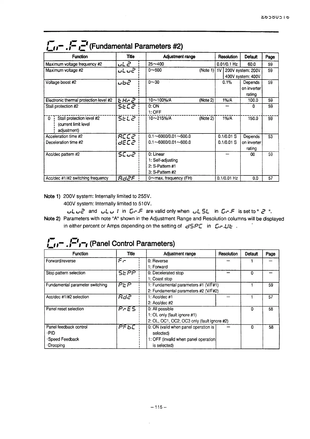
Note 1) 200V system: Internally limited to 255V.
400V system: Internally limited to
51
OV.
Resolution
Default
Page
0.01/0.1
Hz
60.0
59
1V
12oov
system:
2oov
59
400V
system:
400V
0.1%
Depends
59
on
inverter
rating
1%/A
100.0
59
-
0
59
---101~A'---
--------
150.0
59
0.1/0.01
s
Depends
53
0.1/0.01
s
on
inverter
rating
-
00
59
0.1/0.01
Hz
0.0
57
uL
u2
and
ul
u :
in
c.-.F
are valid only when
ul
SL
in
c.-.F
is
set to
II
2
".
Note 2) Parameters with note "A" shown
in
the Adjustment Range and Resolution columns will be displayed
in
either percent or Amps depending on the setting of
dSF'C
in
[,.-.L:::: .
:-.
,-
.1=•
1
-
1
(Panel
Control
Parameters)
-
Function
Tiiie
Adjustment
range
Resolution
Default
Page
Forward/reverse
F,-
I
0:
Reverse
-
1
-
I
I
1:
Forward
I
Stop
pattern
selection
Sl::F'F' I
0:
Decelerated
stop
-
0
-
1 :
Coast
stop
Fundamental
parameter
switching
F'I::
F'
1 :
Fundamental
parameters
#1
(V
/F#1)
1
59
2:
Fundamental
parameters
#2
(V/F#2)
Ace/dee
#1
/#2
selection
F:dc'
1:
Ace/dee
#1
-
1
57
2:
Ace/dee
#2
Panel
reset
selection
F'.-ES
0:
All
possible
0
58
1:
OL
only
(fault
ignore
#1)
2:
OL,
OC1,
OC2,
OC3
only
(fault
ignore
#2)
Panel
feedback
control
C•C
,_ r
I I
WC-
0:
ON
(valid
when
panel
operation
is
-
0
58
·PIO
selected)
·Speed
Feedback
1:
OFF
(invalid
when
panel
operation
·Drooping
is
selected)
-115-

 Loading...


