E6580516
Safety
Precautions
.
This inverter is for driving a 3-phase motor, and must not be used for other applications.
[I)
Always observe the following items to prevent electrical shock.
1.
Do not touch charged parts such as the terminal block while the CHARGE lamp is lit. A charge will still
be present in the electrolytic capacitors, and therafore, touching these areas may result in an electrical
shock.
Always turn inverter's input power off before wiring the motor terminals. Wait at least five
minutes after the
"CHARGE" lamp has gone out, and then confirm that the capacitors have fully
discharged by using a tester, etc., that can measure high-voltage DC.
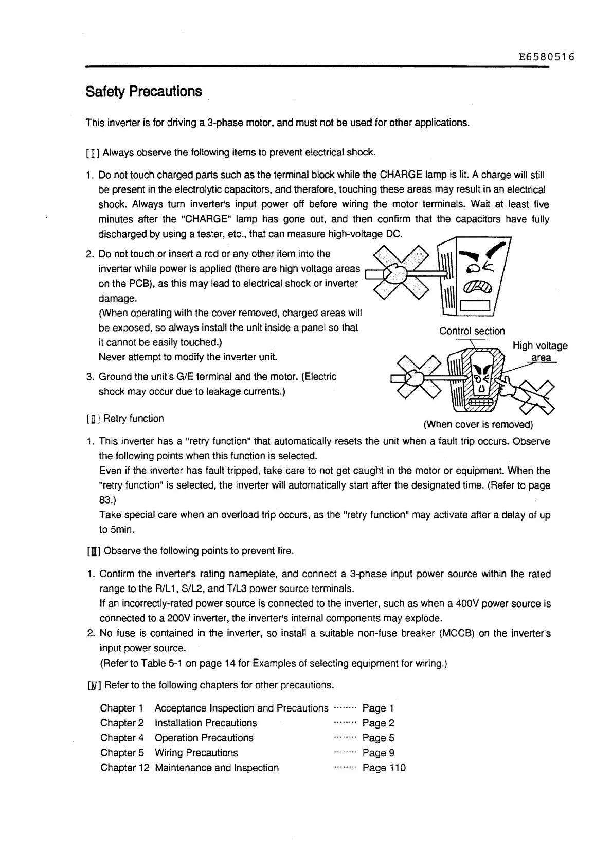
2. Do not touch or insert a rod or any other item into the
inverter
while power is applied (there are high voltage areas
on the
PCB), as this may lead to electrical shock or inverter
damage.
(When operating with the cover removed, charged areas
will
be
exposed, so always install the unit inside a panel so that
it cannot be
easily touched.)
Never attempt to modify the inverter unit.
3.
Ground the unit's G/E terminal and the motor. (Electric
shock may occur due to
leakage currents.)
[
Il
J Retry function
Control section
(When cover is removed)
1. This inverter has a "retry function" that automatically resets the unit when a fault trip occurs. Observe
the
following points when this function is selected.
Even if the inverter has
fault tripped, take care to not get caught in the motor or equipment. When the
"retry function" is selected, the inverter
will automatically start after the designated time. (Refer to page
83.)
Take special care when an overload trip occurs, as the "retry function" may activate after a delay of up
to 5min.
[fil) Observe the following points to prevent fire.
1. Confirm the inverter's rating nameplate, and connect a 3-phase input power source within the rated
range to the R/L
1,
S/L2, and T/L3 power source terminals.
If an incorrectly-rated power source is connected to the inverter, such as when a 400V power source is
connected to a
200V inverter, the inverter's internal components may explode.
2. No fuse is contained in the inverter, so install a suitable non-fuse breaker {MCCB) on the inverter's
input power source.
(Refer to
Table
5-1
on page 14 for Examples of selecting equipment for wiring.)
[}/]
Refer to the following chapters for other precautions.
Chapter 1 Acceptance
Inspection and Precautions ·
··
···· · Page 1
Chapter
2 Installation Precautions Page 2
Chapter 4 Operation Precautions
Chapter 5 Wiring Precautions
Chapter 12 Maintenance and Inspection
Page
5
Page 9
Page 110

 Loading...


