,-
,-
,_,,-
.,-
(Fundamental parameters
#1)
I'=''-
,
,_
V/f
pattem®
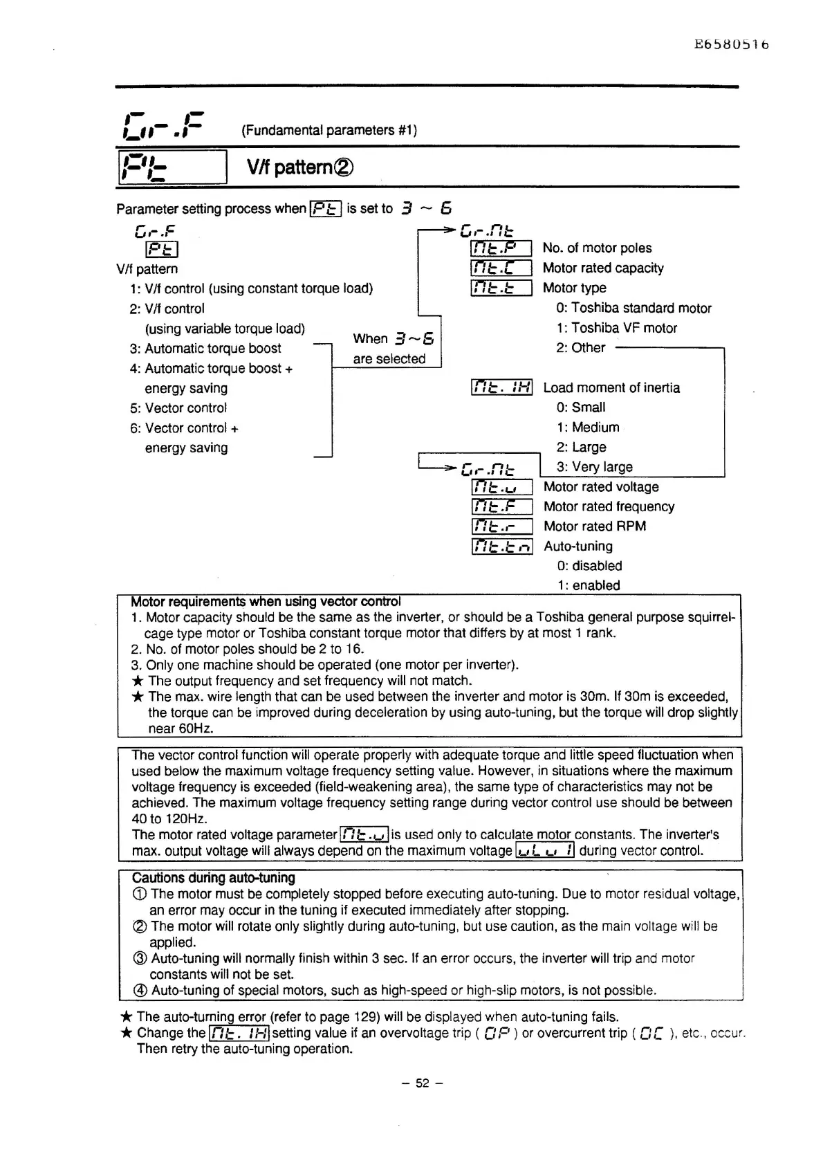
Parameter setting process when
IP
I=
I is set to 3 - 5
c,-.F
IF't:
I
V/f pattern
1:
V /f control {using constant torque load)
2:
V /f control
(using variable torque
load)
3:
Automatic torque boost
4:
Automatic torque boost +
energy saving
5:
Vector control
6:
Vector control +
energy saving
When
3-5
are selected
Motor requirements when using vector control
c,-
.n::
lnt:.P
Int:.[
1n1::.::
No. of motor poles
Motor rated capacity
Motor type
E658051b
O:
Toshiba standard motor
1:
Toshiba
VF
motor
2:
Other
Int:.
IHI
Load moment of inertia
O:Small
c.-
.n1=
lnt:.u
lnt:.F
Int:
.•
-
1:
Medium
2: Large
3:
Very large
Motor rated voltage
Motor rated frequency
Motor rated RPM
Int:./=
.-.I
Auto-tuning
O:
disabled
1:
enabled
1.
Motor capacity should
be
the same as the inverter, or should
be
a Toshiba general purpose squirrel-
cage type motor
or
Toshiba constant torque motor that differs
by
at most 1 rank.
2.
No.
of
motor poles should
be
2 to 16.
3.
Only
one
machine should be operated (one motor per inverter).
* The output frequency and set frequency
will not match.
*The
max. wire length that
can
be used between the inverter and motor is 30m. If 30m is exceeded,
the torque
can
be improved during deceleration by using auto-tuning, but the torque will drop slightly
near
60Hz.
The vector control function will operate properly with adequate torque and little speed fluctuation when
used below the maximum voltage frequency setting value. However,
in
situations where the maximum
voltage frequency is exceeded {field-weakening area), the same type of characteristics may not
be
achieved. The maximum voltage frequency setting range during vector control use should be between
40 to 120Hz.
The motor rated voltage parameter
In
l=
.,_,I
is used only to calculate motor constants. The inverter's
max. output voltage will always depend
on
the maximum
voltagel1_1L
c..1
:I
during vector control.
Cautions
during
auto-tuning
<D
The motor must
be
completely stopped before executing auto-tuning. Due to motor residual voltage,
an
error may occur in the tuning if executed immediately after stopping.
®The
motor will rotate only slightly during auto-tuning, but use caution, as the main voltage
will
be
applied.
<ID
Auto-tuning will normally finish within 3 sec. If
an
error occurs, the inverter will trip and motor
constants will not
be
set.
@)
Auto-tuning of special motors, such as high-speed or high-slip motors, is not possible.
* The auto-turning error (refer to page 129) will
be
displayed when auto-tuning fails.
* Change the
In
l=.
:
HI
setting value if
an
overvoltage trip (
OP)
or
overcurrent trip ( O C
),
etc
.,
occur.
Then retry the auto-tuning operation.
- 52 -

 Loading...


