,-
-
·=
,_
p
1_1
I •
_11_
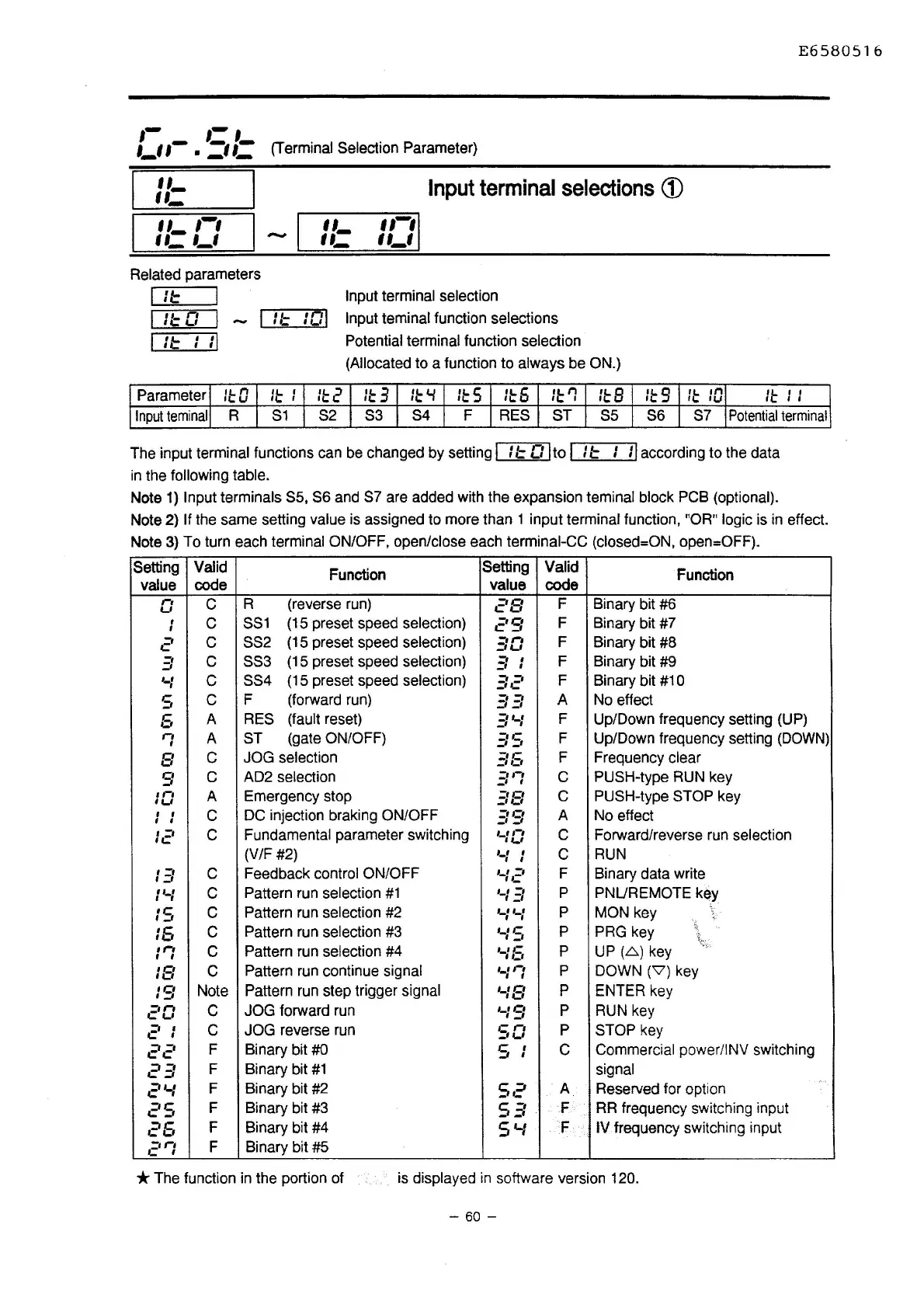
(Terminal Selection arameter)
,,_
,,_
,,_
,-,
,,_
,_,
Related parameters
I
I::
II::
0
11::
•
ti
•
It
Input
terminal
selections
(D
,,_
,,-,
,,_
,,_,
Input terminal selection
:01
Input teminal function selections
Potential terminal function selection
(Allocated
to a function to always be ON.)
E6580516
Parameter
II:
0
II:
I
11:
2
II:
3
II:
'-I
II:
5
II:
6
11:
r:
II:
8
I!.
9
'I:
rti
le;; I
llJ
II:
I I
Input
teminal
R
S1
S2 S3 S4 F RES
ST
SS
S6 S7
Potential
terminal
The input terminal functions can be changed by setting I
It
0 Ito I
It
I
II
according to the data
in
the following table.
Note
1)
Input terminals
SS,
S6 and S7 are added with the expansion teminal block PCB (optional).
Note 2) If the same setting value is assigned to more than 1 input terminal function, "OR" logic is
in
effect.
Note
3)
To turn each terminal ON/OFF, open/close each terminal-CC (closed=ON, open=OFF).
Setting
Valid
Function
Setting
Valid
Function
value
code
value
code
r-1
c
R (reverse run)
c'B
F Binary bit #6
._,
,
c
SS1
(15 preset speed selection)
c'S
F Binary bit #7
I
2
c
SS2 (15 preset speed selection)
30
F Binary bit #8
3
c SS3
(15 preset speed selection)
3 I
F Binary bit #9
._,
I
c
SS4
(15 preset speed selection)
=·
=-
-·~
F
Binary bit #10
s
c
F (forward run)
33
A
No effect
5
A RES (fault reset)
3t...1
F
Up/Down frequency setting (UP)
n
A ST
(gate ON/OFF)
3S
F Up/Down frequency setting
(DOWN)
I
B
c
JOG selection
.=:5
F
Frequency
clear
s
c
AD2 selection
.=:r:
c
PUSH-type RUN key
1n
A Emergency stop
.=:s
c
PUSH-type STOP key
I U
I I
c
DC injection braking ON/OFF
39
A
No effect
I
I
12
c
Fundamental parameter switching
,_,,-,
I W
c Forward/reverse run selection
(V/F #2)
·-:
:
c
RUN
13
c
Feedback control ON/OFF
._:..=·
F
Binary data write
I
t...f
c
Pattern run selection
#1
'-I
El
p
PNUREMOTE key
IS
c
Pattern run selection #2
p
MON key
'
._, ._,
15
c
Pattern run selection #3
'-IS
p
PRG key
•r"•
c
Pattern run selection #4
·-:6
p
UP
(.6.)
key
'
I
18
c
Pattern run continue signal
,_,
,-,
I I
p
DOWN (\7) key
IS
Note
Pattern run step trigger signal
'-18
p
ENTER key
..=·o
c
JOG forward run
'-19
p
RUN key
21
c
JOG reverse run
so
p
STOP key
22
F
Binary bit
#0
s
I
c
Commercial power/INV switching
I
23
F Binary bit
#1
signal
2'-1
F Binary bit #2
s~
-~
A
Reserved for option
c'S
F Binary bit #3
5
-.
;:;
F
RR
frequency switching input
25
F Binary bit #4
5'-1
F IV frequency switching input
c'rl
F Binary bit #5
* The function
in
the portion of
is
displayed
in
software version 120.
- 60 -

 Loading...


