E6580516
1- 1-
I
I
I,-
•
-,
,-
(Terminal Selection Parameters)
- --
,-,,
,-,
·-··=
,_,
'
- -
.......,
,,
__
,
,_,,
__
,
Output
terminal
selections
CD
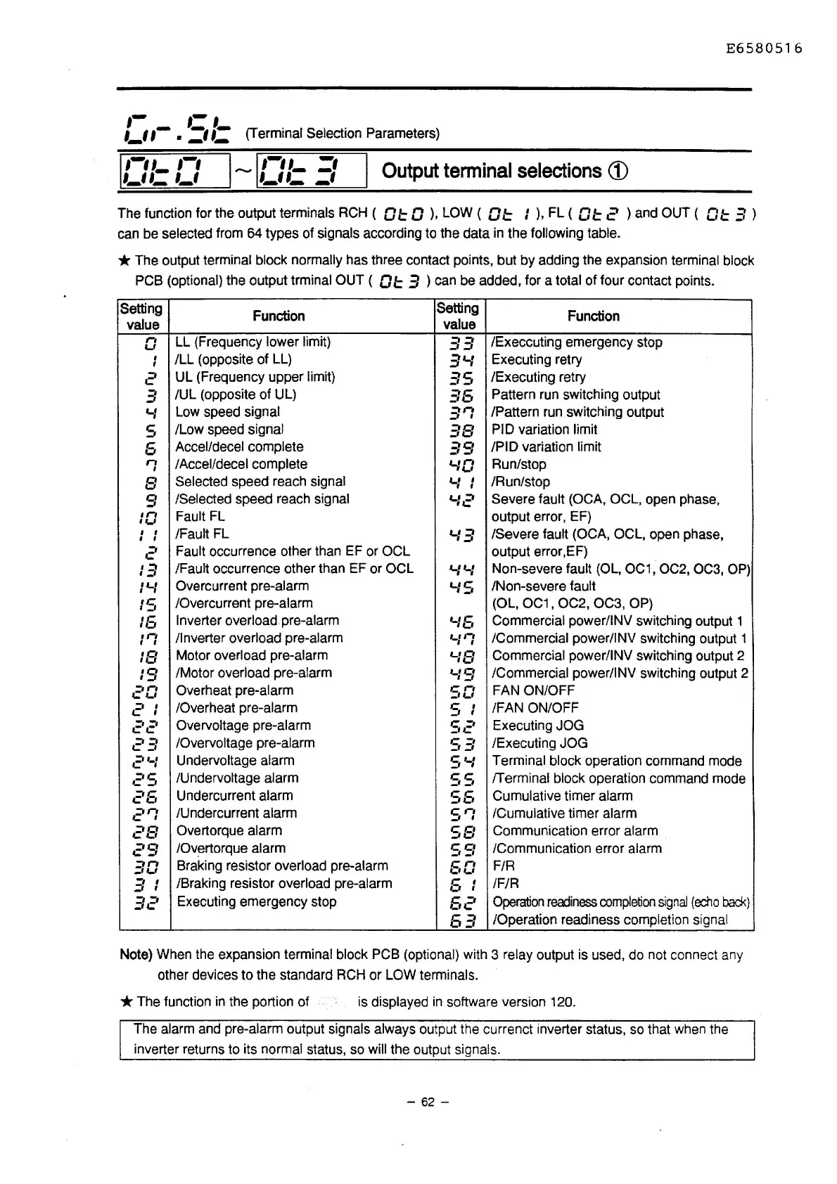
The function for the output terminals RCH ( D
l=
D
),
LOW ( D
l=
I
),
FL ( D
l=
2 ) and OUT ( O t 3 )
can be selected from 64 types of signals according to the data in the following table.
* The output terminal block normally has three contact points, but by adding the expansion terminal block
PCB (optional)
the output trminal OUT (
DI::
3 ) can be added, for a total of four contact points.
Setting
Function
Setting
Function
value
value
n
LL (Frequency lower limit)
33
/Execcuting emergency stop
,_,
I
/LL (opposite of LL)
3'-1
Executing retry
I
2
UL (Frequency upper limit)
.=is
_,
/Executing retry
3
/UL (opposite of UL)
35
Pattern run switching output
'-I
Low speed signal
.=in
-'
I
/Pattern run switching output
s
/Low speed signal
38
Pl D variation limit
6
Accel/decel complete
39
/PIO variation limit
,-,
/Accel/decel complete
'-10
Run/stop
'
8
Selected speed reach signal
r_I
I
I I
/Run/stop
9
/Selected speed reach signal
'-12
Severe fault (OCA, OCL, open phase,
1n
Fault FL output error, EF)
I'-'
I
I
/Fault FL
'-I
.=i
/Severe fault (OCA, OCL, open phase,
I I
_,
c'
Fault occurrence other than EF or OCL
output error,EF)
13
/Fault occurrence other than EF or OCL
'-I
'-I
Non-severe fault (OL, OC1, OC2, OC3,
OP)
I '-I
Overcurrent pre-alarm
'-IS
/Non-severe fault
IS
/Overcurrent pre-alarm (OL,
OC1
, OC2, OC3, OP)
16
Inverter overload pre-alarm
'-16
Commercial power/INV switching output 1
,,-,
/Inverter overload pre-alarm
,_,n
/Commercial power/INV switching output 1
, ,
I I
18
Motor overload pre-alarm
'-18
Commercial power/INV switching output 2
19
/Motor overload pre-alarm
'-19
/Commercial power/INV switching output 2
c'D
Overheat pre-alarm
so
FAN ON/OFF
21
/Overheat pre-alarm
s
I
/FAN ON/OFF
I
22
Overvoltage pre-alarm
S2
Executing JOG
23
/Overvoltage pre-alarm
c
=·
-'~
/Executing JOG
2'-1
Undervoltage alarm
s
'-/
Terminal block operation command mode
c'S
/Undervoltage alarm
SS
/Terminal block operation command mode
c'6
Undercurrent alarm
S6
Cumulative timer alarm
c'r:
/Undercurrent alarm
err
~·
/Cumulative timer alarm
28
Overtorque alarm
S8
Communication error alarm
c'9
/Overtorque alarm
S9
/Communication error alarm
.=in
_,,_,
Braking resistor overload pre-alarm
60
F/R
3 I
/Braking resistor overload pre-alarm
6
I
/F/R
I
32
Executing emergency stop
6c'
Operation
readiness
completion
signal
(echo
bad<)
63
/Operation readiness completion signal
Note) When the expansion
terminal block PCB (optional) with 3 relay output is used, do not connect any
other devices to the standard
RCH or LOW terminals.
* The function
in
the portion of
is displayed
in
software version 120.
The alarm and pre-alarm output signals always output the currenct inverter status, so that when the
inverter returns to its
normal status, so will the output signals.
- 62 -

 Loading...


