E6582175
F-9
6
Set (automatic acceleration/deceleration) to or .
[Parameter setting]
Title Function Adjustment range Default setting
Automatic acceleration/deceleration
0: Disabled (manual setting)
1: Automatic
2: Automatic (only at acceleration)
0
● When automatically setting acceleration/deceleration time, always change the acceleration/deceleration
time so that it conforms to the load. For inverters that require a fixed acceleration/deceleration time, use
the manual settings (, ).
● Setting acceleration/deceleration time (, ) in conformance with mean load allows optimum
setting that conforms to further changes in load.
● Use this parameter after actually connecting the motor.
● When the inverter is used with a load that fluctuates considerably, it may fail to adjust the acceleration or
deceleration time in time, and therefore may be tripped.
● Do not set = when using a dynamic braking resistor (optional).
[Methods of setting automatic acceleration/deceleration]
Operation panel
action
LED display Operation
Displays the output frequency.
(When standard monitor display selection is set to
[output frequency])
The first basic parameter “” (history function) is displayed.
Turn the setting dial to the right to change the parameter to .
Set values are displayed by pressing the center of the setting dial.
Turn the setting dial to the right to switch 1 or .
Press the center of the setting dial to save the changed set value.
and the set value are displayed alternately.
● Assigning the fast stop command 2 (function number 122/ 123) to any logic input terminal, it can be
changed automatic deceleration by compulsion.
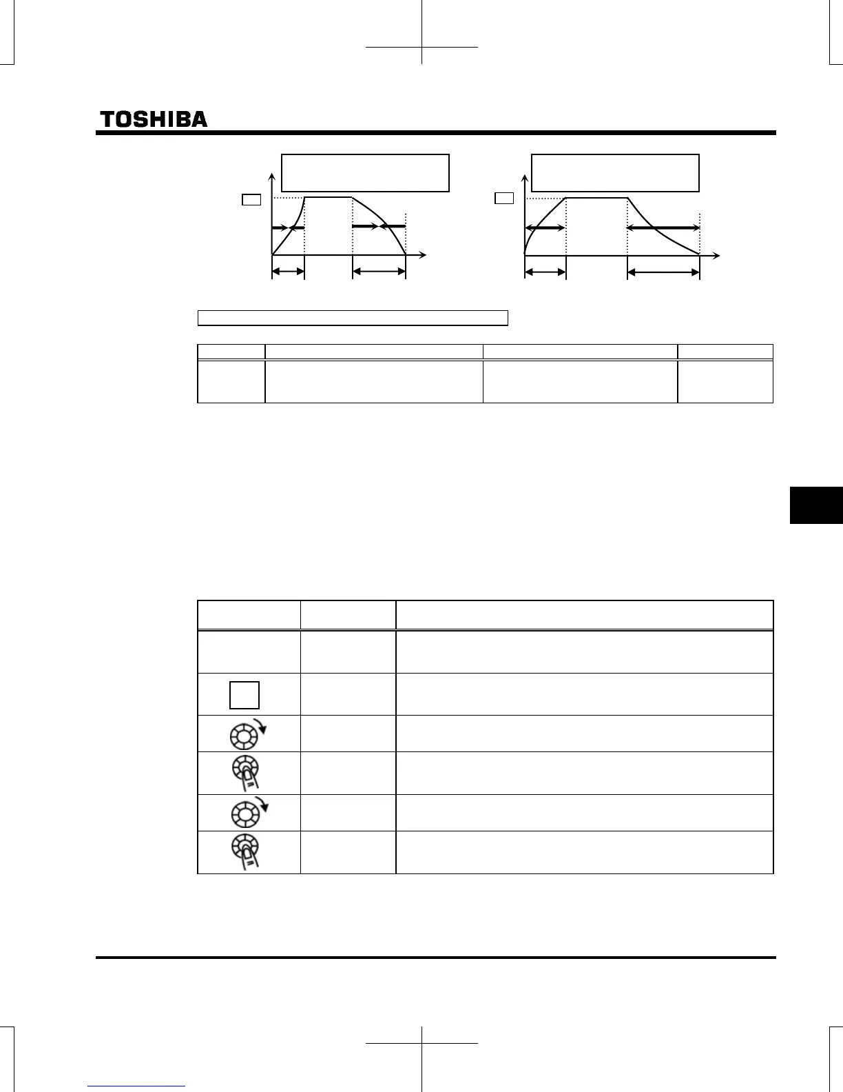
Output
frequency (Hz)
Deceleration
time
Acceleration
time
Example in case the acceleration
and deceleration time become short
Time
[sec]
0
Deceleration
time
cceleration
time
Output
frequency (Hz)
Time
[sec]
0
Example in case the acceleration
and deceleration time become long
MODE

 Loading...


