E6582175
N-5
14
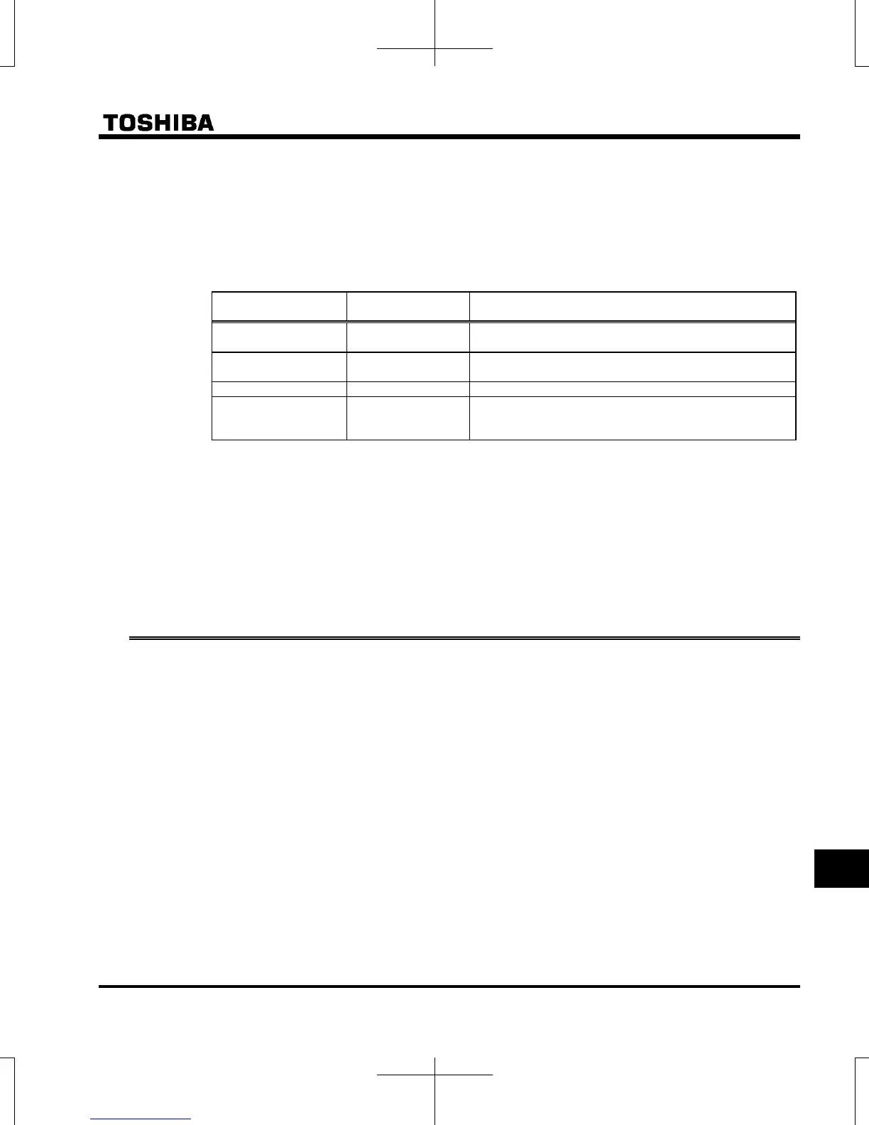
Standard replacement cycles of principal parts
As guides, the table below lists part replacement cycles that were estimated based on the assumption that
the inverter would be used in a normal use environment under normal conditions (ambient temperature,
ventilation conditions, and energizing time). The replacement cycle of each part does not mean its service
life but the number of years over which its failure rate does not increase significantly.
Also, make use of the life alarm function.
Part name
Standard replacement
cycle Note 1,4:
Replacement mode and others
Cooling fan 10 years
Replacement with a new one (To be determined after
inspection)
Main circuit aluminum
electrolytic capacitor
10 years Note 2
Replacement with a new one (To be determined after
inspection)
Relays - Whether to replace or not depends on the check results
Aluminum electrolytic
capacitor mounted on
a printed circuit board
10 years Note 2
Replace with a new circuit board (To be determined after
inspection)
Note 1: The replacement cycle is calculated on the assumption that the average ambient temperature over
a year is 40C and operates 24 hours a day. The environment must be free of corrosive gases, oil
mist and dust.
Note 2: Figures are for when the inverter output current is 80% of the rated current of the inverter.
Note 3: The life of parts varies greatly depending on the operating environment.
Note 4: The standard replacement cycle is not the warranty life time of the inverter.
14.3 Contacting with your Toshiba distributor
If defective conditions are encountered, please contact your Toshiba distributor.
For the Toshiba distributor, refer to the back cover of this instruction manual.
When contacting with your Toshiba distributor, please inform us of the contents of the name plate label on the
right panel of the inverter, the presence or absence of optional devices, etc., in addition to the details of the failure.

 Loading...


