E6582175
G-2
7
7.2 Applied operations by an I/O signal (operation from
the terminal block)
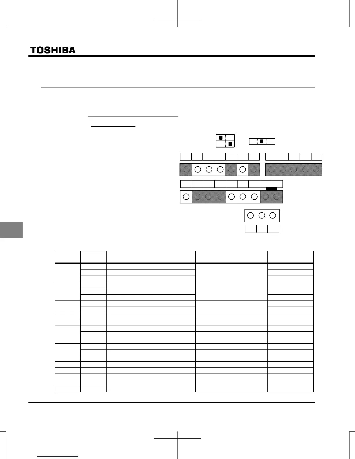
Input terminal sink and source logic are set by using slide switch SW1.
7.2.1 Input terminal function
(sink logic)
This function is used to send a signal to the
input terminal from an external programmable
controller to operate or configure the inverter.
The ability to select from a variety of functions
allows for flexible system design.
Default settings of slide switch SW1and SW2 are
as follows;
SW1: PLC side, SW2: VIB side and S3 side.
Refer to page B-11 to 13 for details.
Settings for the logic input terminal function
Terminal
symbol
Title Function Adjustment range Default setting
F
Input terminal selection 1A (F)
0-203 Note 1)
2 (F)
Input terminal selection 1B (F) 0 (No function)
Input terminal selection 1C (F) 0 (No function)
R
Input terminal selection 2A (R)
0-203 Note 1)
4 (R)
Input terminal selection 2B (R) 0 (No function)
Input terminal selection 2C (R) 0 (No function)
RES
Input terminal selection 3A (RES)
0-203 Note 1)
8 (RES)
Input terminal selection 3B (RES) 0 (No function)
S1
Input terminal selection 4A (S1)
0-203 Note 1)
10 (SS1)
Input terminal selection 4B (S1) 0 (No function)
S2
Input terminal selection 5 (S2) 0-203 Note 3) 12 (SS2)
f146
Logic input / pulse train input
selection (S2)
0: Logic input
1: Pulse train input
0
S3
Input terminal selection 6 (S3) 0-203 Note 4) 14 (SS3)
f147
Logic input / PTC input selection (S3) 0: Logic input
1: PTC input
0
VIB
Input terminal selection 7 (VIB) 0-203 Note 5) 16 (SS4)
VIA
Input terminal selection 8 (VIA) 8-55 Note 6) 24 (AD2)
VIA
VIB
Analog/logic input selection (VIA/VIB) 0-4 0
F to VIB
Input terminal response time 1-1000 (ms) Note 7) 1
VIC
FM
S3
FLA
RY
FLC
FLB
VIA CC
VIB
PP
RC
FCC R
NO
P24
OUT
STO
CC
+SU
S2
RES
S1
SINK
SOURCE
SW1
PLC
VIB
SW2
PTC
S3
S4
[Control terminal block]

 Loading...


