E6582175
F-19
6
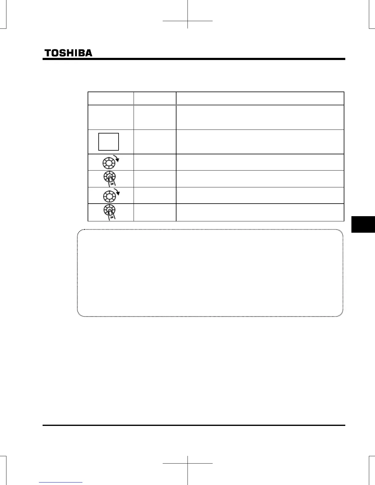
Steps in setting are as follows
(In this example, the V/F control mode selection parameter is set to (Vector control).
[Setting V/F control mode selection to 3 (sensorless vector control)]
Operation panel
action
LED display Operation
.
Displays the output frequency. (Perform during operation stopped.)
(When standard monitor display selection is set to
[output frequency])
The first basic parameter “” (history function) is displayed.
Rotate the setting dial to the right, and change the parameter to
(V/F control mode selection).
Set values are displayed by pressing the center of the setting dial.
Rotate the setting dial to the right, and change the parameter to
(vector control).
Press the center of the setting dial to save the changed set value.
and the set value “” are displayed alternately.
Caution:
When the V/F control mode selection is set to : Automatic torque boost control, : Vector control,
: Energy-saving, : Dynamic energy-saving, or : PM motor control, be sure to set the following
parameters according to the motor's name plate.
: Base frequency 1 (rated frequency)
: Base frequency voltage 1 (rated voltage)
: Motor rated capacity
: Motor rated current
: Motor rated speed
Set the other motor constants as necessary
MODE

 Loading...


