E6582175
F-42
6
Adjustment with continuous signals (Operation example 1)
Set parameters as follows to adjust the output frequency up or down in proportion to the frequency
adjustment signal input time:
External logic input up/down frequency incremental gradient = f265/f264 setting time
External logic input up/down frequency decremental gradient = f267/f266 setting time
Set parameters as follows to adjust the output frequency up or down almost synchronously with the
adjustment by the external logic input up/down frequency command:
f264 = f266 = 0.1
(fh/acc) (f265/f264 setting time)
(fh/dec) (f267/f266 setting time)
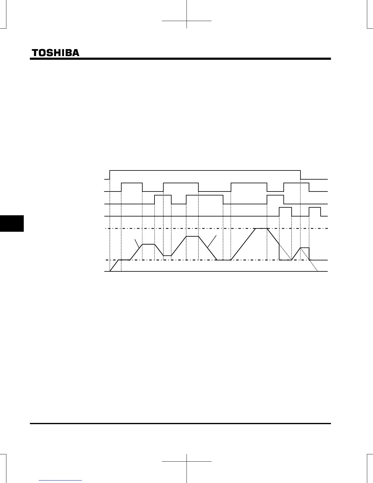
<<Sample sequence diagram 1: Adjustment with continuous signals>>
The dotted line denotes the output frequency obtained by combining the slowdown speed and the
panel frequency adjustment speed.
Frequency 0 Hz
Lower limit frequency
Gradient f267/f266
Gradient f265/f264
Upper limit frequency
DOWN signal
UP signal
Forward / reverse command
Set frequency clearing signal
Adjustment with pulse signals (Operation example 2)
Set parameters as follows to stepwise adjust the frequency by one pulse:
f264, f266 ≤ Pulse On time
f265, f267 = Frequency obtained with each pulse
* The inverter does not respond to any pulses with an ON time shorter than that set with f264 or
f266. 12ms or more of clearing signal is allowed.

 Loading...


