E6582175
J-2
10
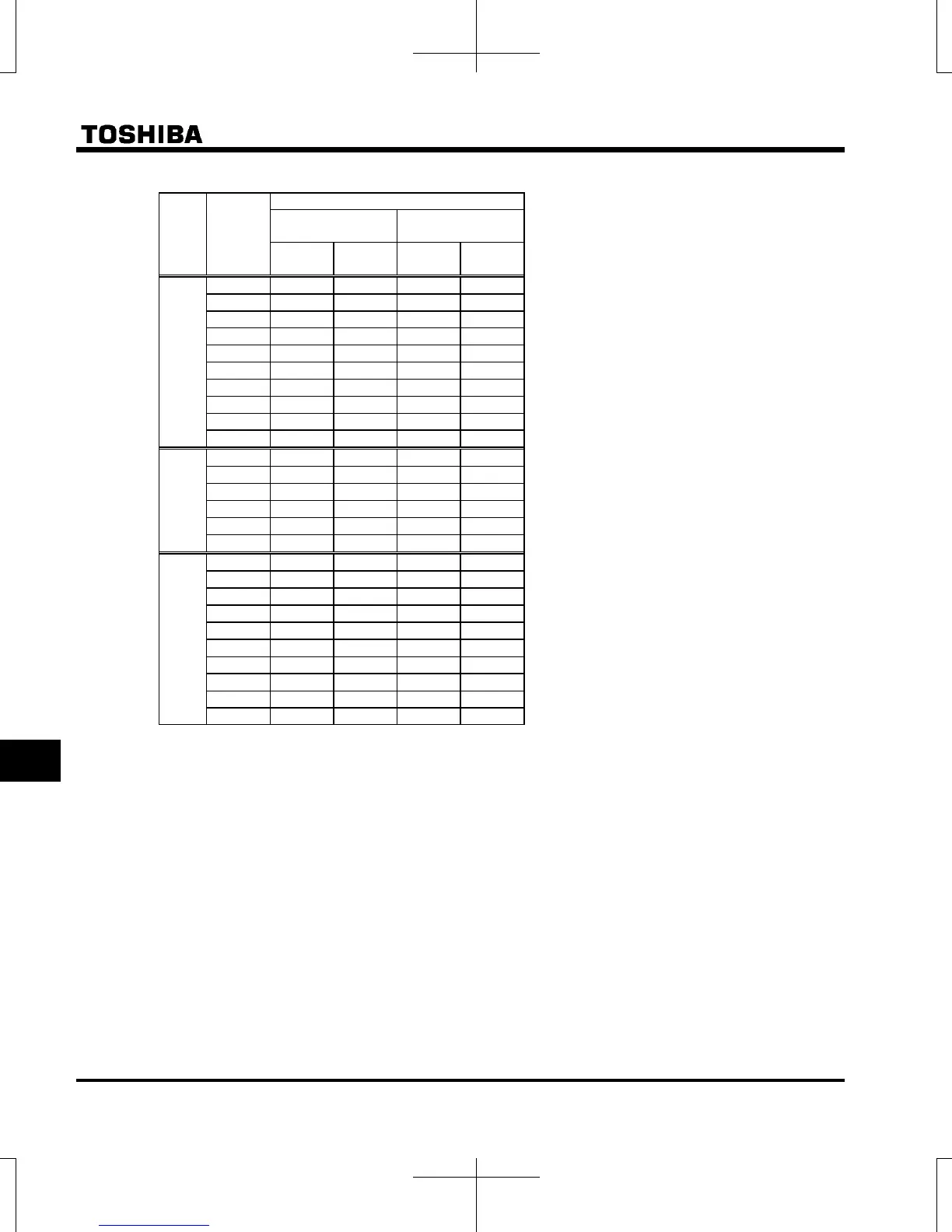
Voltage
class
Applicable
motor
(kW)
Wire size (mm
2
) Note 4)
Braking resistor
(optional)
Grounding cable
IEC
Compliant
For Japan
*1
IEC
Compliant
For Japan
*1
3 phase
240V
class
0.4 1.5 2.0 2.5 2.0
0.75 1.5 2.0 2.5 2.0
1.5 1.5 2.0 2.5 2.0
2.2 1.5 2.0 2.5 2.0
4.0 2.5 2.0 4.0 3.5
5.5 4.0 2.0 10 5.5
7.5 6.0 3.5 16 5.5
11 16 5.5 16 8.0
15 25 14 16 8.0
18.5 25 14 25 8.0
1 phase
240V
class
0.2 1.5 2.0 2.5 2.0
0.4 1.5 2.0 2.5 2.0
0.75 1.5 2.0 2.5 2.0
1.5 1.5 2.0 2.5 2.0
2.2 1.5 2.0 4.0 3.5
3.0 1.5 2.0 4.0 3.5
3 phase
500V
Class
0.4 1.5 2.0 2.5 2.0
0.75 1.5 2.0 2.5 2.0
1.5 1.5 2.0 2.5 2.0
2.2 1.5 2.0 2.5 2.0
4.0 1.5 2.0 2.5 2.0
5.5 1.5 2.0 4.0 3.5
7.5 2.5 2.0 6.0 3.5
11 4.0 2.0 10 5.5
15 6.0 3.5 16 5.5
18.5 10 5.5 16 5.5
*1: For Japan: JEAC8001-2005 compliant
Note 1: Sizes of the wires connected to the input terminals R/L1, S/L2 and T/L3 (Single-phase models are R/L1
and S/L2/N) and the output terminals U/T1, V/T2 and W/T3 when the length of each wire does not exceed
30m. If there is a need to bring the inverter into UL compliance, use wires specified in chapter 9.
Note 2: For the control circuit, use shielded wires 0.75 mm
2
or more in diameter.
Note 3: For grounding, use wires with a size equal to or larger than the above.
Note 4: The wire sizes specified in the above table apply to HIV wires (copper wires shielded with an insulator
with a maximum allowable temperature of 75°C) used at an ambient temperature of 50°C or less.
Note 5: In case of aul=2 setting, contact your Toshiba distributor for wire size.

 Loading...


