E6582175
A-23
1
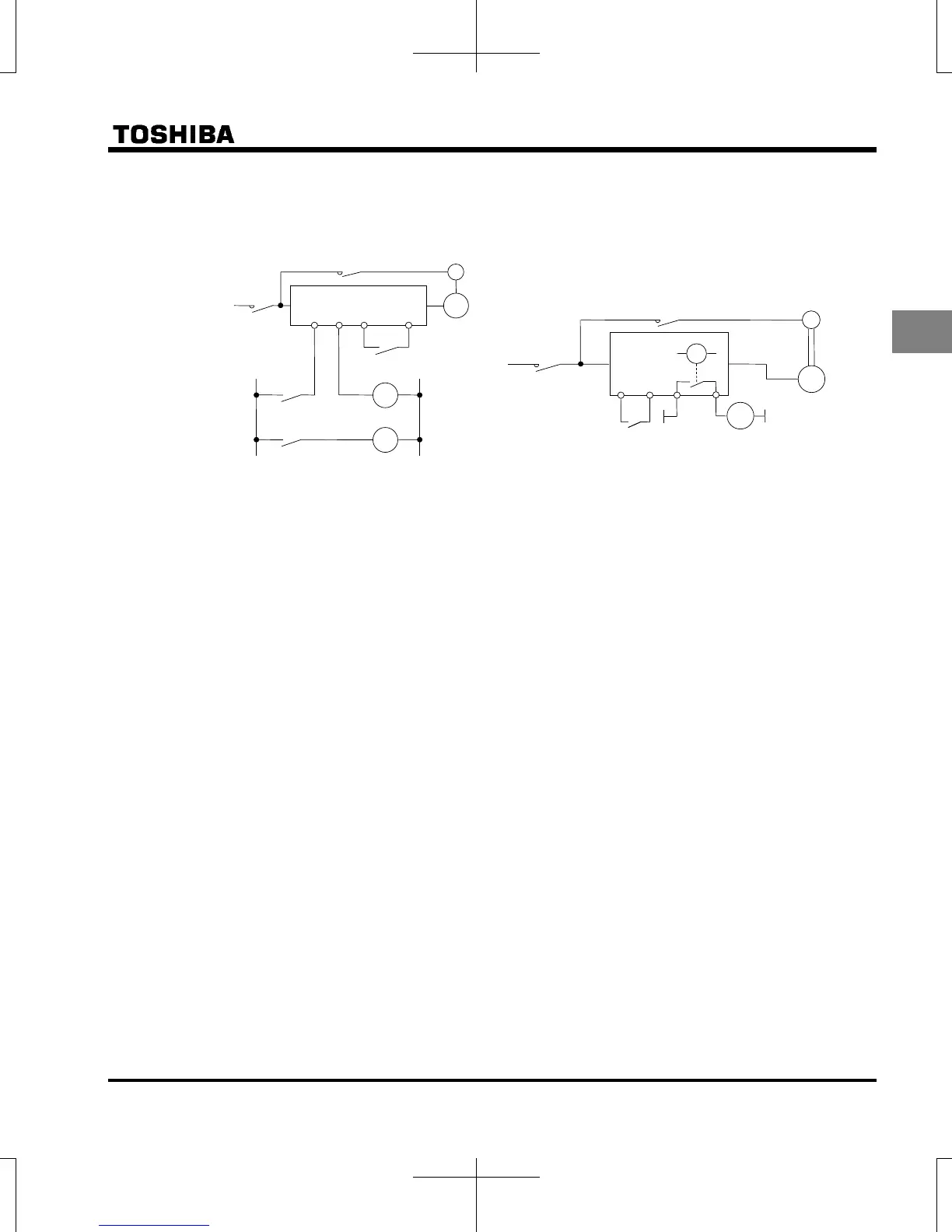
Motors with a brake
When motors with a brake are directly connected to the inverter's output, the brake cannot be released
at startup because of low voltage. Wire the brake circuit separately from the main circuit.
In circuit diagram 1, the brake is turned on and off through MC2 and MC3. If you do not wire it as shown
in diagram 1, an over-current trip may occur because of a bound current during brake operation.
(Example of standby ST assigned to terminal S2.)
In circuit diagram 2, the brake is turned on and off by using low-speed signal RY-RC. (Refer to section
6.5.1)
In some situations, such as with elevators, turning the brake on and off with a low-speed signal may be
appropriate. Be sure to contact us before designing your system.
Measures to protect motors against surge voltages
In a system in which a 500V-class inverter is used to control the operation of a motor, very high surge
voltages may be produced. When applied to the motor coils repeatedly for a long time, may cause
deterioration of their insulation, depending on the cable length, cable routing and types of cables used.
Here are some examples of measures against surge voltages.
(1) Lower the inverter’s carrier frequency.
(2) Set the parameter
f316 (Carrier frequency control mode selection) to any one from 2 to 5.
(3) Use a motor with high insulation strength.
(4) Insert an AC reactor or a surge voltage suppression filter between the inverter and the motor.
MC2
B
IM
MC1
3-phase
power
source
FLB FLC S2(ST)
CC
MC3
MC3
MC2
Circuit diagram 1
MC1
MC3
Power
supply
MC1
MC2
IM
B
F CC
RY
MC2
RY
Run / stop
Non-excitation activation
type brake
RC
Circuit diagram 2

 Loading...


