E6582175
M-7
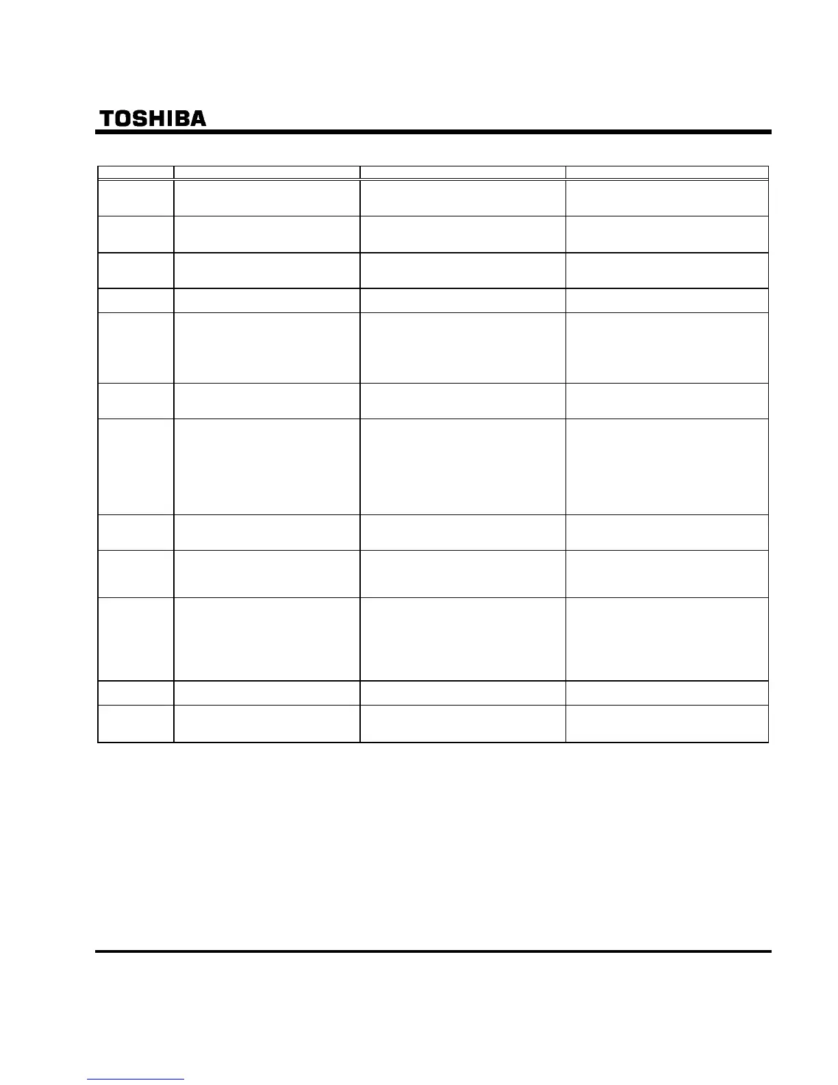
[Alarm information] Each message in the table is displayed to give a warning but does not cause the inverter to trip.
Error code Name Description Remedies
Output frequency upper limit
An attempt was made to operate at a
frequency higher than 10 times the base
frequency ( or ).
Operate at a frequency within 10 times
the base frequency.
Operation panel key alarm
The RUN or STOP key is held down for
more than 20 seconds.
The RUN or STOP key is faulty.
Check the operation panel.
S3 terminal alarm
Slide switch SW2 and parameter f147
settings are different.
Match the settings of SW2 and f147.
Power supply OFF and ON after these
settings.
Auto-tuning
Auto-tuning in process Normal if it the message disappears after
a few seconds.
Break in analog signal cable
The signal input via VIC is below the
analog signal detection level set with
and setting value of is
one or more.
Check the cables for breaks. And check
the setting of input signal or setting value
of and .
This alarm is cancelled, when operation
command is OFF after VIC input signal is
recovered.
In forced operation
“” and operation frequency is
displayed alternately in operation of
forced fire-speed control.
It is normal the alarm is gone out after the
forced fire-speed control operation.
STO signal OFF
STO terminal is in open-circuit.
Input voltage of STO terminal is low.
The voltage of P24 terminal decreases.
The load of P24 terminal (24Vdc power
supply) is over 100mA.
Control terminal block comes off.
Close STO and + SU circuit.
Check the load of P24 terminal, if STO
and +SU is shorted.
Check the load of P24 terminal.
Use P24 terminal up to 100mA including
transient current.
Install the control terminal block to the
inverter.
/
Password verification result
After the password setting (f738), the
password was input to f739 (password
verification).
If the password is correct, pass is
displayed and if it is incorrect, fail is
displayed.
/
Switching display of
Easy setting mode / Standard setting
mode
The EASY key was pushed in the
standard monitor mode.
When easy is displayed, setting
mode becomes easy setting mode.
When std is displayed, it becomes
standard setting mode.
Note 2)
Input requirement of region setting
A region setting is not input yet.
Power supplied to the inverter at first time
As checking the region setting parameter
set is set to 0, inverter return to default
setting.
As typ is set to 13, inverter return to
default setting.
Set a region setting by using setting
dial.
Refer to section 3.1.
No trip of past trip
No new record of past trip, after past trips
were clear.
Normal operation.
No detailed information of past trip
The detailed information of past trip is
read by pushing the center of setting dial
during blinking nerr ⇔ number.
Normal operation.
To be returned by pressing MODE key.
Note 2) is blinking after power supply is on. In this time, the keys are not operated.
But parameter set is lighting as same as other parameters and is not blinking.

 Loading...


