E6582175
B-10
2
Terminal
symbol
Input /
output
Function
Electrical
specifications
Inverter internal circuits
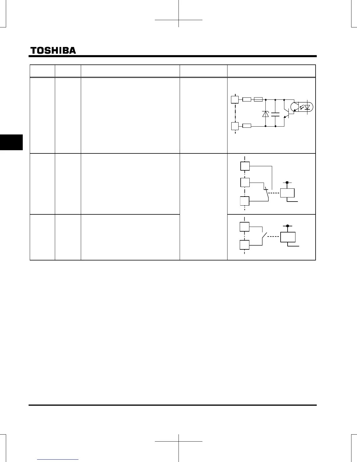
OUT
NO
Output
Multifunction programmable open
collector output. Default setting detect
and output speed reach signal.
Multifunction output terminals to which
two different functions can be assigned.
The NO terminal is an equipotential
terminal. It is isolated from the CC
terminal.
By changing parameter f669 settings,
these terminals can also be used as
multifunction programmable pulse train
output terminals.
Open collector
output
24Vdc-100mA
To output pulse
trains,
a current of 10mA
or more needs to
be passed.
Pulse frequency
range:
10~2kpps
FLA
FLB
FLC
Note 3)
Output
Multifunction programmable relay contact
output.
Detects the operation of the inverter's
protection function.
Contact across FLA-FLC is closed and
FLB-FLC is opened during protection
function operation.
Max. switching
capacity
250Vac-2A,
30Vdc-2A
(cos=1)
: at resistive load
250Vac-1A
(cos=0.4)
30Vdc-1A
(L/R=7ms)
Min. permissible
load
5Vdc-100mA
24Vdc-5mA
RY
RC
Note 3)
Output
Multifunction programmable relay contact
output.
Default settings detect and output low-
speed signal output frequencies.
Multifunction output terminals to which
two different functions can be assigned.
Note 1) When VIA terminal is used as logic input terminal, be sure to connect a resistor between P24 and VIA in case of sink
logic, between VIA and CC in case of source logic. (Recommended resistance: 4.7kΩ-1/2W)
It is not needed for VIB terminal.
Note 2) When STO terminal is used as the safety function, refer to Safety function manual (E6581860).
Note 3) A chattering (momentary ON/OFF of contact) is generated by external factors of the vibration and the impact, etc. In
particular, please set the filter of 10ms or more, or timer for measures when connecting it directly with input unit terminal
of programmable controller. Please use the OUT terminal as much as possible when the programmable controller is
connected.
4.7
NO
PTC
OUT
4.7
+24V
RY
RC
+24V
FLB
FLA
FLC

 Loading...


