EasyManuals Logo

Toshiba Tosvert VF-S15 User Manual

Toshiba Tosvert VF-S15
394 pages
To Next Page IconTo Next Page
To Previous Page IconTo Previous Page
Page #58 background imageLoading...
Page #58 background image
E6582175
B-12
2
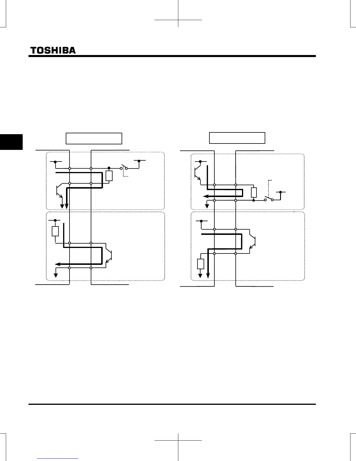
<Examples of connections when an external power supply is used>
The P24 terminal is used as common terminal to connect to an external power supply or to separate a
terminal from other input or output terminals.
Note 5) Do not shut down the external power supply on ahead when VIA terminal is used as logic input
terminal by external power supply in SINK logic connection. It could cause unexpected result as
VIA terminal is ON status.
Sink (Negative) logic
Slide switch SW1 : PLC side
Source (Positive) logic
Slide switch SW1 : PLC side
24VDC
In
p
ut
In
p
ut
24V
DC
24V
DC
Output
Output
Inverter
Programmable
controller
SW1:PLC side
Common
Common
F
P24
OUT
NO
F
Output
In
p
ut
24V
DC
Out
p
ut
OUT
NO
24VDC
In
p
ut
Common
Inverter
Programmable
controller
P24
Common
24VDC
SW1:PLC side

Table of Contents

Other manuals for Toshiba Tosvert VF-S15

Questions and Answers:

Question and Answer IconNeed help?

Do you have a question about the Toshiba Tosvert VF-S15 and is the answer not in the manual?

Toshiba Tosvert VF-S15 Specifications

General IconGeneral
CategoryInverter
Control MethodV/f control, Sensorless vector control
Cooling MethodForced air cooling
ModelTosvert VF-S15
Protection FeaturesOvercurrent, Overvoltage, Undervoltage, Overheat
Communication OptionsModbus RTU
Overload Capacity150% for 1 minute
Braking UnitBuilt-in braking transistor
Output Voltage3-Phase, same as input voltage
Operating Temperature-10 to +50°C (14 to 122°F)
Storage Temperature-20 to 65°C (-4 to 149°F)
Humidity5 to 95% RH (non-condensing)
AltitudeUp to 1000m above sea level
Input Voltage3-Phase 200 to 240 VAC, 3-Phase 380 to 480 VAC
WeightVaries depending on model (e.g., 0.8 kg to 16 kg)

Related product manuals