Installation: Mechanical
CVHH-SVX001A-EN 19
location, contact Trane. For more information, refer to
“ Factory Warranty Information,” p. 4.
Unit Isolation
To m inimize sound and vibration transm ission through the
building structure, and to ensure proper weight
distribution over the mounting surface, always install
isolation pads or spring isolators under the chiller feet.
Note: Isolation pads (see
Figure 6) are provided w ith each
chiller unless spring isolators are specified on the
sales order.
Specific isolator loading data is provided in the unit
submittal package. If necessary, contact your local Trane
sales office for further information.
Important: When determining placement of isolation
pads or spring isolators, remember that the
control panel side of the unit is always
designated as the unit front.
Isolation Pads
When the unit is ready for final placement, position
isolation pads (457.2-mm sides) end for end under the full
length of the chiller leg. The pads measure 228.6 mm x
457.2 mm (9 in. × 18 in.) and on some units there may be
small gaps between pads. Pads are provided to cover
entire foot.
Remember that the chiller must be level within 1.6 mm
(1/16 in.) over its length and width after it is lowered onto
the isolation pads. In addition, all piping connected to the
chiller must be properly isolated and supported so that it
does not place any stress on the unit.
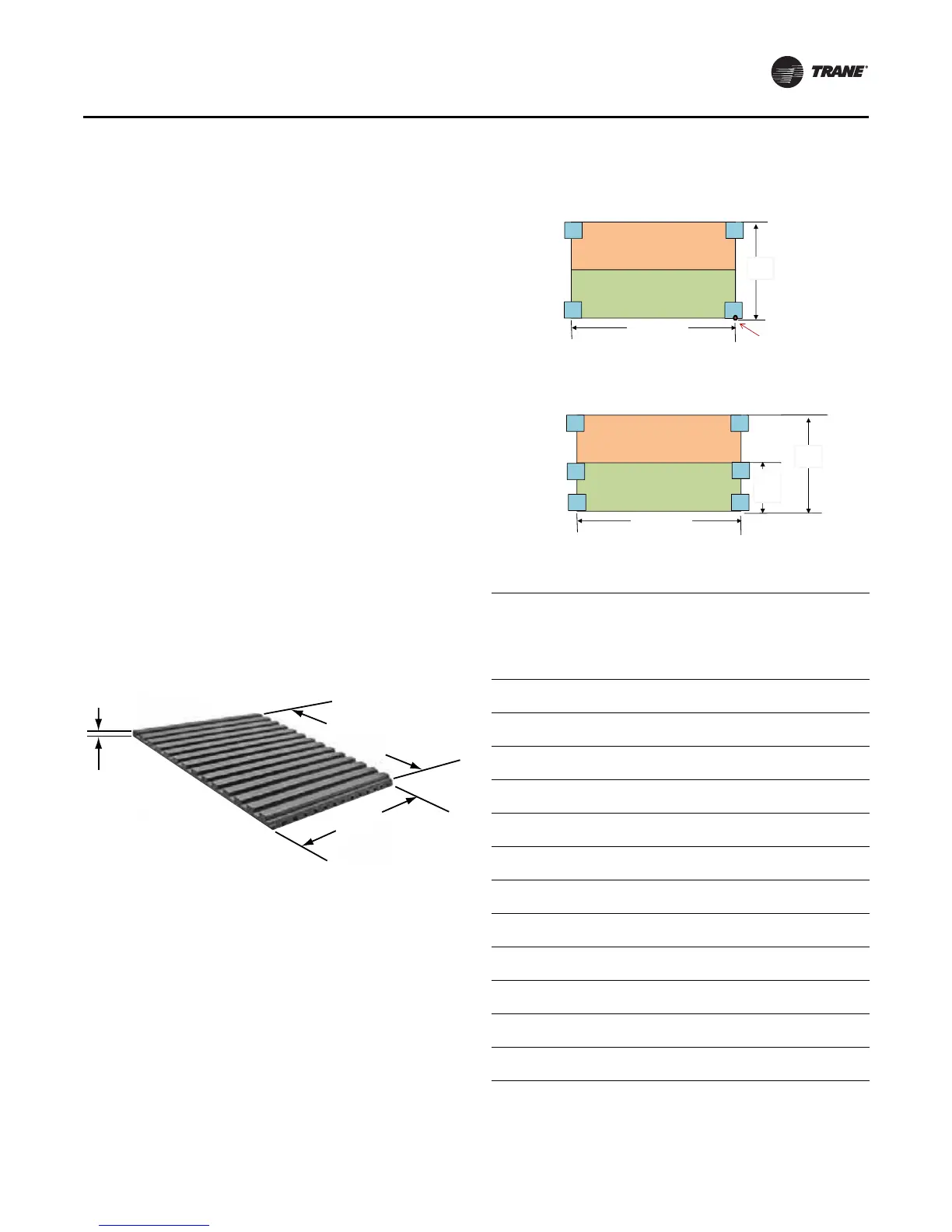
Spring Isolators
Spring isolators should be considered whenever chiller
installation is planned for an upper story location. Base
isolator placement is shown in
Figure 7; also refer to
Tab l e 3.
Spring isolators typically ship assembled and ready for
installation. To install and adjust the isolators properly,
follow the instructions given.
Figure 6. Isolation pad and dimensions
228.6 mm
(9 in.)
457.2 mm
(18 in.)
9.525 mm
(3/ 8 in.)
Figure 7. Isolation spring placement by shell size,
evaporator and condenser length
Table 3. Isolation spring placement, cm (in.)
EVSZ CDSZ W idth
Evap
W idth Length
I solator
Config
Origin
to
Center
o f R ear
P ad
Origin
to
Center
of
Middle
Pad
200L 200L
285.0
(112.2)
170.2
(67)
457.2
(180)
2
268.5
(105.7)
153.7
(60.5)
220L 220L
303.3
(119.4)
188.0
(74)
457.2
(180)
2
286.8
(112.9)
171.5
(67.5)
200L 20HL
336.0
(132.3)
170.2
(67)
457.2
(180)
2
319.5
(125.8)
153.7
(60.5)
220L 22HL
361.0
(142.5)
188.0
(74)
457.2
(180)
2
345.4
(136)
171.5
(67.5)
160M 20HM
323.3
(127.3)
154.9
(61)
406.4
(160)
2
306.8
(120.8)
138.4
(54.5)
200L 220L
285.2
(112.3)
170.2
(67)
457.2
(180)
2
268.7
(105.8)
153.7
(60.5)
160M 200M
270.3
(106.4)
154.9
(61)
406.4
(160)
2
253.7
(99.9)
138.4
(54.5)
100M 100M
264.4
(104.1)
N/ A
406.4
(160)
1
247.9
(97.6)
N/ A
100L 100L
264.4
(104.1)
N/ A
457.2
(180)
1
247.9
(97.6)
N/ A
130M 130M
277.6
(109.3)
N/ A
406.4
(160)
1
261.1
(102.8)
N/ A
100M 10HM
300.2
(118.2)
N/ A
406.4
(160)
1
283.7
(111.7)
N/ A
130M 13HM
313.4
(123.4)
N/ A
406.4
(160)
1
296.9
(116.9)
N/ A
Condenser
Evaporator
Length
2
5
1
4
6
3
Width
I solator Configuration 1
Origin:
Right front corner of
evap right front foot
Condenser
Evaporator
Length
2
5
1
4
6
3
Evap
Width
Width
I solator Configuration 2