Start-up and Shut-down
78 CVHH-SVX001A-EN
If the STOP key is pressed on the operator interface, the
chiller will follow the same stop sequence as above except
the chilled water pump relay will also open and stop the
chilled water pump after the chilled water pump delay
timer has timed out after compressor shut down (see
Figure 45).
If the “ Immediate Stop” is initiated, a panic stop occurs
which follows the same stop sequence as pressing the
STOP key once except the inlet guide vanes are not
sequence closed and the compressor motor is
immediately turned off.
Power Up Diagram
Figure 42, p. 76 illustrates Tracer AdaptiView during a
power up of the main processor. This process takes from
30 to 50 seconds depending on the number of installed
Options. On all power ups, the software model always will
transition through the Stopped software state
independent of the last mode. If the last mode before
power down was Auto, the transition from Stopped to
Starting occurs, but it is not apparent to the user.
Ice Machine Control
The control panel provides a service level Enable or
Disable menu entry for the Ice Building feature when the
Ice Building option is installed. Ice Building can be entered
from Front Panel, or if hardware is specified the control
panel will accept either an isolated contact closure 1K9
Terminals J2-1 and J2-2 (Ground)) or a remote
communicated input (BAS) to initiate the ice building
mode where the unit runs fully loaded at all times. Ice
building will be terminated either by opening the contact
or based on entering evaporator fluid temperature. The
control panel will not permit the Ice Building mode to be
entered again until the unit is switched to the non-ice
building mode and back into the ice building m ode. It is not
acceptable to reset the chilled water setpoint low to
achieve a fully loaded compressor. When entering ice
building, the compressor will be loaded at its maximum
rate and when leaving ice building the compressor will be
unloaded at its maximum rate. While loading and
unloading the compressor, all surge detection will be
ignored. While in the ice building mode, current limit
setpoints less than the maximum will be ignored. Ice
Building can be terminated by one of the following means:
• Front panel disable.
• Opening the external Ice. Contacts/ Remote
communicated input (BAS).
• Satisfying an evaporator entering fluid temperature
setpoint (default is -2.8°C [27°F]).
• Surging for 7 minutes at full open IGV.
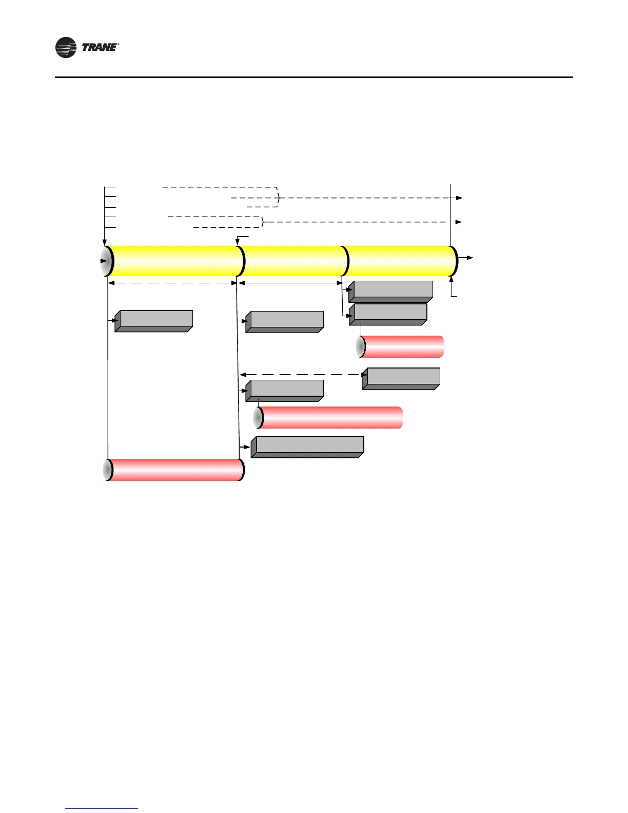
Figure 45. Sequence of operation: normal shut-down to stopped and run inhibit
Local Stop
Normal Latching Diagnostic
Normal Non-Latching Diagnostic
Tracer Stop
External Auto-Stop
IGV Closed
Preparing Shutdown Shutting Down
Shutting Down
Running
Stopped
Run Inhibit
Stopped
or
Run Inhibit
Evap Pump
Off Delay
and Postlube
Complete
Close IGV (0–50 sec)
Postlube 3 min
Evap Pump Off Delay Time
(0–30 min)
Command IGV Closed
Enforce All Running Mode Diagnostics
De-Energize Condenser
Water Pump Relay
De-Energize
Compressor
Confirm No Compressor Currents
Within 8 sec
Hold position of Oil Vent Line Valve
Open Oil Vent Line Valve
De-Energize Oil Pump
Confirm No Oil Pressure*
5 min after oil pump
is de-energized
De-Energize Evaporator
Water Pump Relay
*Note: No oil pressure is less than 20.7 kPad (3 psid)