Power Supply Wiring
58 CVHH-SVX001A-EN
Terminal Clamps
Note: Graphic labels (shown above) are used for CE
application only.
Important:
• Before servicing, disconnect all power sources and
allow at least 30 minutes for capacitors to discharge.
• All electrical enclosures—unit or remote—are IP2X.
Terminal clamps are supplied with the motor terminals to
accommodate either bus bars or standard motor terminal
wire lugs. Terminal clamps provide additional surface area
to minimize the possibility of improper electrical
connections.
Wire Terminal Lugs
Wire terminal lugs must be field supplied.
• Use field-provided, crimp-type wire terminal lugs
properly sized for the application.
Note: Wire size ranges for the starter line and load-
side lugs are listed on the starter submittal
drawings supplied by the starter manufacturer
or Trane. Carefully review the submitted wire
lug sizes for compatibility with the conductor
sizes specified by the electrical engineer or
contractor.
• On 600 V and below, a terminal clamp with a
9.525-mm (3/8-in.) bolt is provided on each motor
terminal stud; use the factory-supplied Belleville
washers on the wire lug connections.
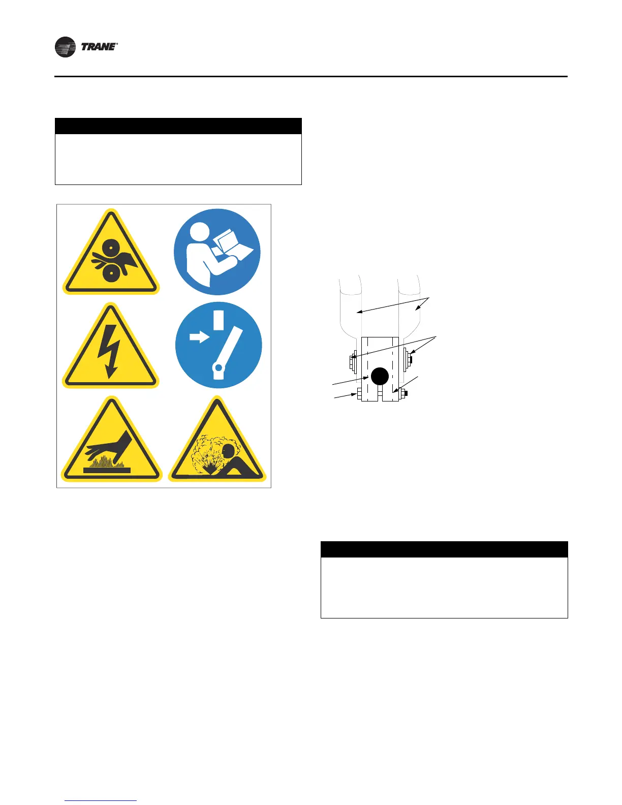
Figure 32
illustrates the junction between a motor terminal stud
and terminal lug.
• Torque for this assembly is 32.5 N·m (24 ft·lb).
• Install but do not connect the power leads between the
starter and compressor motor. (These connections will
be completed under supervision of a qualified Trane
service engineer after the pre-start inspection.)
Bus Bars
Bus bars and extra nuts are available as a Trane option.
Install the bus bars between the motor terminals when
using a starter that is:
• a low-voltage AFD
• across-the-line
• primary reactor/resistor
• auto transformer
• customer-supplied
NOTICE:
Use Copper Conductors Only!
Failure to use copper conductors could result in
equipment damage as unit terminals are not designed
to accept other types of conductors.
Figure 32. Terminal stud, clamp, and lug assembly
(600 V and below)
1. Belleville washer
2. Terminal lugs
3. Terminal clamp
4. Motor terminal stud
5. Terminal mounting bolt
NOTICE:
Component Damage!
Failure to ensure the power supply wiring and output to
motor wiring are connected to the proper terminals.
could cause catastrophic failure of the starter and/ or
motor.