Vent Piping
34 CVHH-SVX001A-EN
Trane RuptureGuard
General Information
The Trane RuptureGuard™ refrigerant containment
system replaces the rupture disk on new low pressure
chillers utilizing R-1233
zd
(E). The RuptureGuard system
consists of a solid-metal, (non-fragmenting) reverse-
buckling rupture disk, and automatically re-seating relief
valve. The relief valve and the rupture disk are rated at the
chiller’s maximum working pressure level. If the chiller’s
refrigerant pressure exceeds the rupture disk burst rating,
the disk bursts, releasing pressure to the relief valve. The
relief valve vents the pressure down to a safe level and
then re-seats, thus minimizing the amount of refrigerant
vented to the atmosphere.
Figure 21 illustrates the
operation of a reverse buckling rupture disk.
To prevent water, refrigerant and/or other debris such as
rust from hindering the operation of the valve, a drip leg
should be installed immediately after or downstream of
the RuptureGuard (see
Figure 22).
Connection to External Vent Line and Drip
Leg
With RuptureGuard installed horizontally, the drain plug
downstream of the valve relief plug and nearest to the
bottom of the valve body should be piped to the drip leg
in the vent line. This will allow the removal of any
condensate formed within the valve body.
Provisions, such as installing a set of flanges (see
Figure 22) or other disconnect m eans, must be made in the
discharge vent piping. This will allow the piping
downstream of the valve to be easily removed for an
annual inspection, to replace the rupture disk, or for any
other servicing need.
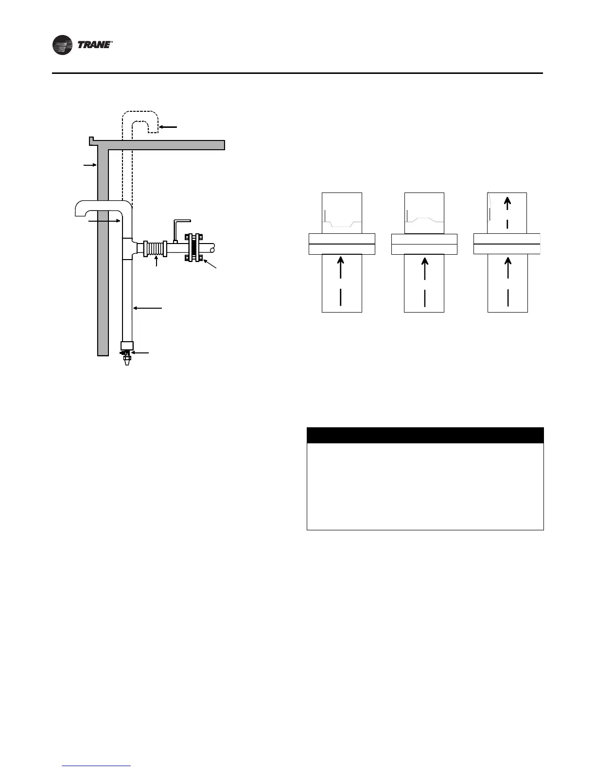
Figure 20. Arrangement for rupture disk relief piping
Alternate
Purge discharge
vent line
Outside
wall
Support
this pipe
Flexible
steel
connection
Drip leg
(length as required
for easy access)
1/ 4 in. FL x 1/ 4 in. NPT
drain valve
Rupture disk
assembly
Figure 21. Reverse buckling rupture disk
NOTICE:
Equipment Damage!
Trane assumes no responsibility for equipment damage
caused by insufficient drainage of drip leg. All vent lines
must be equipped with a drip leg of sufficient volume
to hold the expected accumulation of water and/or
refrigerant. The drip leg must be drained periodically to
assure that it does not overflow and allow fluid to flow
into the horizontal portion of the vent line.
Chiller
ChillerChiller
Flow
Flow
Flow
Flow
Flow
Disk in normal
operating position.
Chiller pressure is
below 50 psig.
The disk snaps
open through the
score line of the
outlet ring and the
pr essure is vent ed.
The outlet ring is
designed with a
h in g e ar ea t o r etai n
the disk petal.
When chiller
pressure exceeds
the disk’s rated
burst pressure, t he
disk begins to tear
open along the
score line of the
outlet ring.
Flow
Flow
Flow
Flow
Flow
Chiller
Chiller Chiller