Operating Principles
68 CVHH-SVX001A-EN
Oil and Refrigerant Pump
Compressor Lubrication System
A schematic diagram of the compressor lubrication
system is illustrated in
Figure 38, p. 69. Oil is pumped from
the oil tank (by a pump and motor located within the tank)
through an oil pressure regulating valve designed to
maintain a net oil pressure of 137.9 to 165.5 kPad (20 to
24 psid). It is then filtered and sent to the braze plate heat
exchanger oil cooler located above the oil tank and on to
the compressor motor bearings. From the bearings, the oil
drains back to the oil tank.
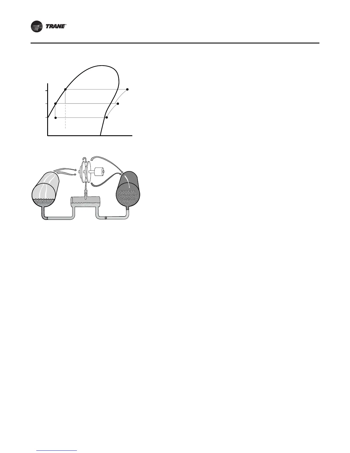
Figure 36. Pressure enthalpy curve
Figure 37. Refrigerant flow, 2-stage
condenser
economizer
evaporator
2
3
4
P
1
P
2
P
3
Pressure
compressor
(2nd stage)
compressor
(1st stage)
1
5
6