Start-up and Shut-down
76 CVHH-SVX001A-EN
There are five generic states that the software can be in:
•Power Up
•Stopped
•Starting
• Running
•Stopping
Descriptions
• The time line indicates the upper level operating mode,
as it would be viewed on Tracer AdaptiView.
• The shading color of the cylinder indicates the
software state.
• Text in parentheses indicates sub-mode text as viewed
on Tracer AdaptiView.
• Text above the time line cylinder is used to illustrate
inputs to the Main Processor. This may include User
input to the Tracer AdaptiView Touch screen, Control
inputs from sensors, or Control Inputs from a Generic
BAS.
• Boxes indicate Control actions such as Turning on
Relays, or moving the Inlet Guide Vanes.
• Smaller cylinders indicate diagnostic checks, text
indicates time based functions, solid double arrows
indicate fixed timers, and dashed double arrows
indicate variable timers.
Start-up Sequence of Operation—
Wye-Delta
Logic Circuits within the various modules will determine
the starting, running, and stopping operation of the chiller.
When operation of the chiller is required the chiller mode
is set at “Auto.” Using customer supplied pow er, the chilled
water pump relay is energized and chilled water flow must
be verified within 4 minutes and 15 seconds, at the same
time the oil vent line valve is opened. The main processors
logic decides to start the chiller based on the differential to
start setpoint. With the differential to start criteria met, the
module then energizes condenser water pump relay with
customer supplied power (see
Figure 42, p. 76).
Based on the Restart Inhibit function and the Differential to
Start setpoint, the oil and refrigerant pump is energized,
and the oil vent line valve is closed to the minimum
position. The oil pressure must be at least 82.7 kPad
(12 psid) for 60 continuous seconds and condenser water
flow verified within 4 minutes and 15 seconds for the
compressor start sequence to be initiated. After the
compressor starts, the oil vent line valve begins to open;
it can take between 15 and 30 minutes to fully open
depending on the chiller running conditions.
The compressor motor starts in the “ Wye” configuration
and then, after the compressor motor has accelerated and
the maximum phase current has dropped below
85 percent of the chiller nameplate RLA for 1.5 seconds,
the starter transitions to the “ Delta” configuration.
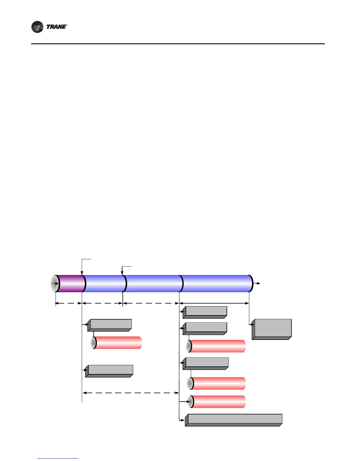
Figure 42. Sequence of operation: power up to starting
Power
Applied
to
Controls
Last Chiller Mode
Was Auto
Call for Cooling
Auto Waiting to Start
Waiting to Start
Starting
Compressor
UC800 Boot
Time
(30–50 sec)
Enforce Power
Up Start Delay
Timer (0–30 min)
Wait for Highest Motor Winding
Temp to Fall Below 73.9°C (165°F)
Wait for Oil Temp to Rise Above
Sat Evap + -1.1°C (30°F)
and 37.8°C (100°F)
Prelube (60 sec)
Begin Oil Vent Line
Valve low limit
venting
Overdrive IGV Closed
Energize Condenser
Water Pump Relay
Confirm Condenser Water Flow
Within 4 min 15 sec
(6 sec Filter)
Energize Oil Pump Relay
Confirm 82.7 kPad (12 psid)
Oil Pressure
Within 3 min
Check for High Vacuum
Lockout
Initialize Oil Vent Line Valve to Minimum Open Position
Energize Evaporator
Water Pump Relay
Confirm Evaporator Water
Flow Within 4 min 15 sec
(6 sec Filter)
Open Oil Vent Line Valve
Enforce Stop to Start Timer Using Values From
Real Time Clock (5–200 sec, 30 is Default)