Installation: Water Piping
28 CVHH-SVX001A-EN
Victaulic Gasket Installation
1. Inspect supplied gasket to be certain it is suited for
intended service (code identifies gasket grade). Apply
a thin coat of silicone lubricant to gasket tips and
outside of gasket.
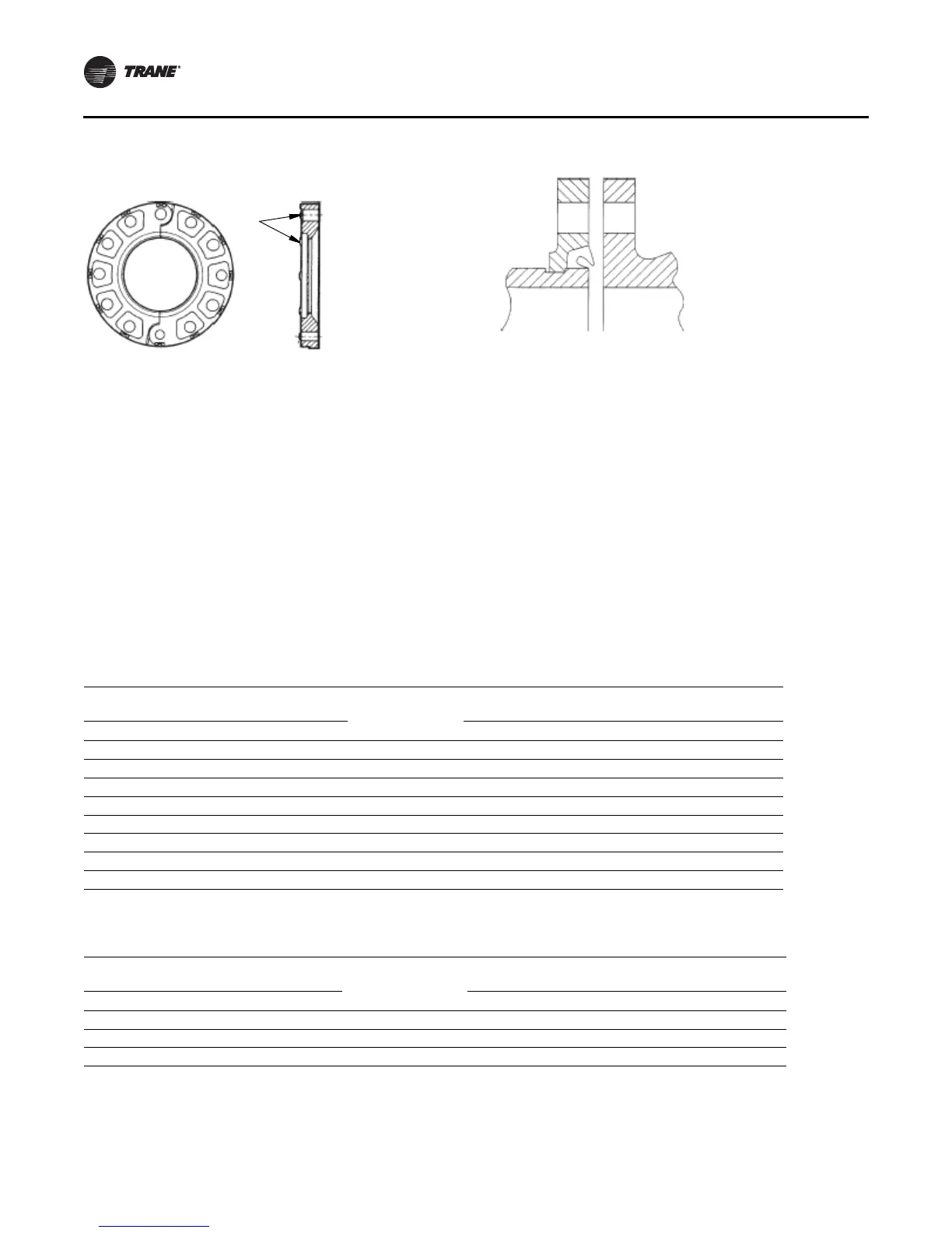
2. Install gasket, placing gasket over pipe end and making
sure gasket lip does not overhang pipe end. Refer to
Figure 18 for gasket configuration.
3. Align and bring two pipe ends together and slide
gasket into position centered between the grooves on
each pipe. No portion of the gasket should extend into
the groove on either pipe.
4. Open fully and place hinged Victaulic flange around
the grooved pipe end with the circular key section
locating into the groove.
5. Insert a standard bolt through the mating holes of the
Victaulic flange to secure the flange firmly in the
groove.
6. Tighten fasteners alternately and equally until housing
bolt pads are firmly together (metal to metal); refer to
“ Bolt-Tightening Sequence for Water Piping
Connections,” p. 29
. Do not excessively tighten
fasteners.
Note: Uneven tightening may cause gasket to pinch.
Figure 17. Modifying 300 psig or 21 bar flange adaptors
for flat-faced flange application
Rem o v e to ma t e
to flat-faced
flanges
Figure 18. Typical Victaulic flange gasket configuration
Table 6. Installation data for 150 psig flange adapters (Style 741)
Nom inal Pipe Size
Assembly Bolt
Size
( a)
Num ber of
Assembly Bolts
Required
Bolt Pattern Diam eter W eight
mm in. in. mm in. kg lb
200 8 3/4 x 3-1/ 2 8 298 11.75 7.5 16.6
250 10 7/ 8 x 4 12 362 14.25 11 24.2
300 12 7/ 8 x 4 12 432 17 21.2 46.8
350 14 1 x 4-1/ 2 12 476 18.75 28.1 62
400 16 1 x 4-1/ 2 16 540 21.25 35.8 79
450 18 1-1/8 x 4-3/ 4 16 578 22.75 37.3 82.3
500 20 1-1/8 x 5-1/ 4 20 635 25 46.9 103.3
600 24 1-1/4 x 5-3/ 4 20 749 29.5 64.4 142
(a) Bolt size for conventional flange to flange connection. Longer bolts are required when flange washer must be used.
Table 7. Installation data for 350 psig flange adapters (Style 743)
Nom inal Pipe Size
Assem bly Bolt
Size
( a )
Num ber of
Assembly Bolts
Required
Bolt Pattern Diam eter W eight
mm in. in. mm in. kg lb
219.1 8 3/ 4 x 4-3/ 4 12 330 13 15.6 34.3
273.0 10 1 x 5-1/ 4 16 387 15.25 21.9 48.3
323.9 12 1-1/ 8 x 5-3/ 4 16 451 17.75 32.0 70.5
(a) Bolt size for conventional flange to flange connection. Longer bolts are required when flange washer must be used.