Installation: Controls
42 CVHH-SVX001A-EN
Communication Interfaces
There are four connections on the UC800 that support the
communication interfaces listed. Refer to
Figure 26, p. 41
for the locations of each of these ports.
•BACnet MS/TP
• MODBUS Slave
• LonTalk using LCI-C (from the IPC3 bus)
• Comm 4 using TCI (from the IPC3 bus)
Rotary Switches
There are three rotary switches on the front of the UC800
controller. Use these switches to define a three-digit
address when the UC800 is installed in a BACnet or
MODBUS system (e.g., 107, 127, etc.).
Note: Valid addresses are 001 to 127 for BACnet and 001
to 247 for MODBUS.
LED Description and Operation
There are 10 LEDs on the front of the UC800.
Figure 27
shows the locations of each LED and
Table 11, p. 42
describes their behavior in specific instances.
Important: Maintain at least 16 cm (6 in.) between low-
voltage (<30V) and high voltage circuits.
Failure to do so could result in electrical
noise that could distort the signals carried
by the low-voltage wiring, including IPC.
1. Rotary Switches for setting BACnet
®
MAC address or MODBUS
®
ID.
2. LINK for BACnet MS/TP, or MODBUS Slave (two terminals, ±). Field
wired if used.
3. LINK for BACnet MS/TP, or MODBUS Slave (two terminals, ±). Field
wired if used.
4. Machine bus for existing machine LLIDs (IPC3 Tracer bus 19.200 baud).
IPC3 Bus: used for Comm4 using TCI or LonTalk
®
using LCI-C.
5. Power (210 mA at 24 Vdc) and ground terminations (same bus as
item 4). Factory wired.
6. Not used.
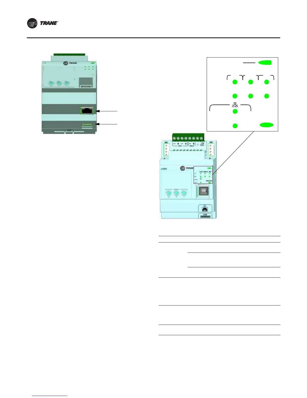
7. Marquee LED power and UC800 Status indicator (
Tab l e 11, p. 42).
8. Status LEDs for the BAS link, MBus link, and IMC link.
9. USB device type B connection for the service tool (Tracer TU).
10. The Ethernet connection can only be used with the Tracer AdaptiView
display.
11. USB Host (not used).
Figure 26. Wiring locations and connection ports
Figure 27. LED locations
Table 11. LED behavior
LED UC8 00 Status
Marquee LED
Pow ered. If the Marquee LED is green solid, the
UC800 is powered and no problems exist.
Low pow er or malfunction. If the Marquee LED is
red solid, the UC800 is powered, but there are
problem s present.
Alarm . The Marquee LED blinks Red when an alarm
exists.
LINK, MBUS,
IMC
The TX LED blinks green at the data transfer rate
when the UC800 transfers data to other devices on
the link.
The Rx LED blinks yellow at the data transfer rate
when the UC800 receives data from ot her devices on
the link.
Ethernet Link
The LI NK LED is solid green if the Ethernet link is
connected and communicating.
The ACT LED blinks yellow at the data transfer rate
when data flow is active on the link.
Service
The Service LED is solid green when pressed. For
qualified service technicians only. Do not use.
LINK
LINK MBUS IMC
TX
RX
ACT
SERVICE