System Control Circuit Wiring (Field Wiring)
64 CVHH-SVX001A-EN
Water Pump Interlock Circuits and Flow
Switch Input
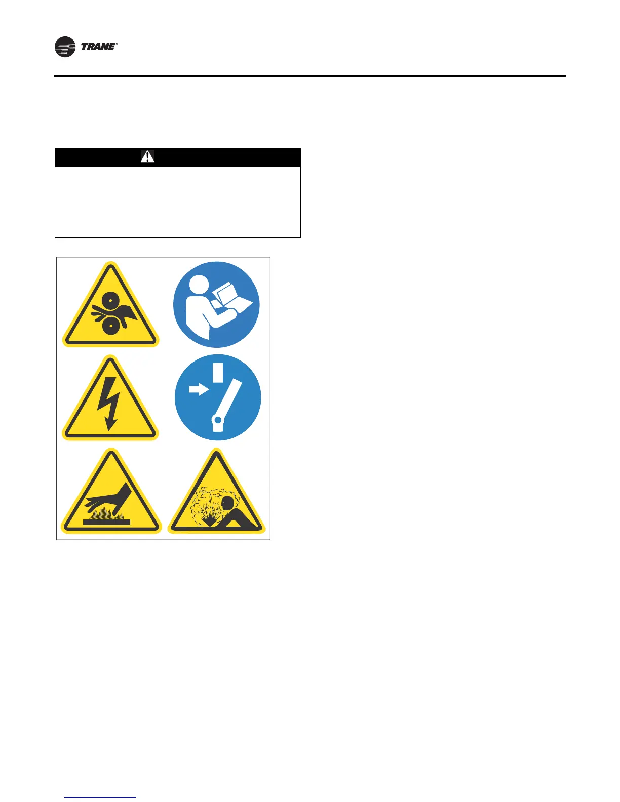
Note: Graphic labels (shown above) are used for CE
application only.
Important:
• Before servicing, disconnect all power sources and
allow at least 30 minutes for capacitors to discharge.
• All electrical enclosures—unit or remote—are IP2X.
Note: The circuits for the chilled water proof of flow and
the condenser water proof of flow do NOT require
external power. Refer to the wiring diagrams that
shipped with the chiller.
Chilled water pump
1. Wire the evaporator water pump contactor (5K42) to a
separate 120 volt single phase power supply with
14 AWG, 600 volt copper wire. For AWG/MCM
equivalents in mm
2
, refer to
Table 12, p. 47.
2. Connect circuit to 1K15-J2-6.
3. Use 1K15-J2-4 120 Vac output to allow the control
panel to control the evaporator water pump, or wire
the 5K1 contactor to operate remotely and
independently of the control panel.
Chilled water proof of flow
When this circuit is installed properly and the evaporator
pump is running and providing the required minimum
flow, this circuit will prove the evaporator water flow for
the chiller controls. Proof of evaporator water flow is
required before the start sequence will be allowed to
proceed and a loss of evaporator water flow during chiller
operation will result in a chiller shut-down.
Refer to as-built schematics on the inside of the control
panel for field wiring. This is a dry binary input; normally-
open, closure for flow. Apply no external power.
1. With factory-installed ifm efector flow-sensing
devices, a field-provided secondary flow-sensing
device is recommended with applications having 3.3°C
(38°F) and below leaving evaporator water
temperatures. When a secondary flow-sensing device
is used, remove the factory jumper and install its
contacts between 1X1-5 to 1K26-4; this places the
secondary flow sensing device in series with the
ifm efector.
2. For field-provided primary proof of flow devices,
connect the primary proof of flow device between
terminals 1X1-5 to 1K16-J3-2. A secondary field device
is recommended with applications having 3.3°C (38°F)
and below leaving evaporator water temperatures,
and must be field-wired in series with the primary
proof of flow device.
Condenser water pump
1. Wire the condenser water pump contactor (5K43) to a
separate 120-volt, single phase power supply with
14 AWG, 600-volt copper wire. For AWG/MCM
equivalents in mm
2
, refer to
Table 12, p. 47.
2. Connect circuit to control panel terminals 1K15-J2-3.
3. Use 1K15-J2-1 120 Vac output to allow the control
panel to control the condenser pump.
Condenser water proof of flow
When this circuit is installed properly and the condenser
pump is running and providing the required minimum
condenser water flow, this circuit will prove the condenser
water flow for the chiller controls. Proof of condenser
water flow is also required for the start sequence will be
allowed to proceed and a loss of condenser water flow
during chiller operation will result in a chiller shut-down.
Refer to as-built schematics on the inside of the control
panel for field wiring. This is a dry binary input; normally-
open, closure for flow. Apply no external power.
(c) Standard low-voltage circuits (less than 30 Vac) m ust be separated from 120 Vac or higher wiring.
WARNING
Hazardous Voltage!
Failure to disconnect power before servicing could
result in death or serious injury. Disconnect all electric
power, including remote disconnects before servicing.
Follow proper lockout/ tagout procedures to ensure the
power can not be inadvertently energized.