Installation: Controls
CVHH-SVX001A-EN 45
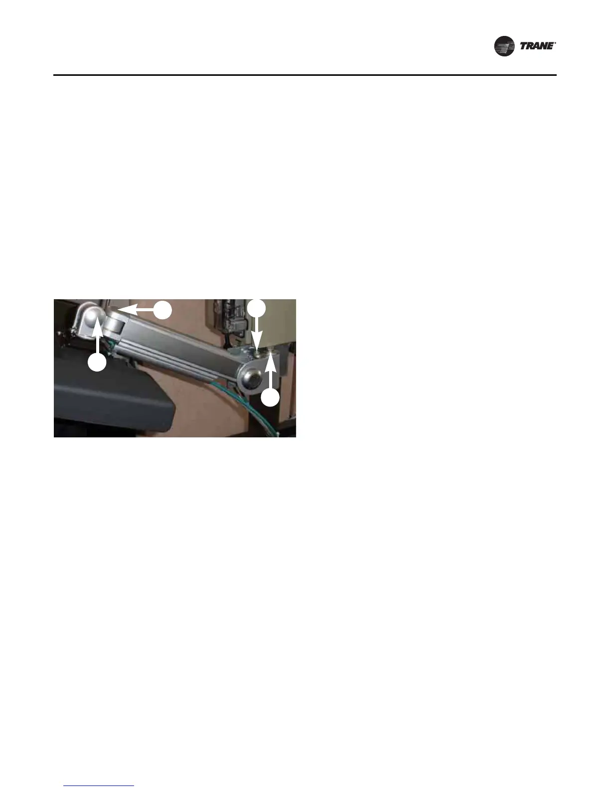
Adjusting the Tracer AdaptiView
Display Arm
The Tracer AdaptiView display arm may become too loose
or too tight and need adjustment. There are three joints on
the display arm that allow the Tracer AdaptiView display to
be positioned at a variety of heights and angles (refer to
items labeled 1, 2, and 3 in
Figure 29).
To adjust the tension on the display arm:
• At each joint in the display arm, there is either a hex
bolt (1 and 2) or hex screw (3). Turn the hex bolt or
screw in the proper direction to increase or decrease
tension.
Note: Each hex bolt or screw is labeled with loosen/
tighten or +/- indicators.
• Joint 3 has a 6 mm hex screw controlling the tension
on a gas spring, which allows the Tracer AdaptiView
display to tilt up and down.
• Joints 1 and 2 are covered by a plastic cap. Remove the
plastic cap to access the hex bolt. Adjust using a 13 mm
wrench as necessary.
• To adjust the swivel rotation tension of the Tracer
AdaptiView display, adjust the hex bolt located in the
support arm base plate, as described in
Step 8 in
“ Installing the Tracer AdaptiView Display,” p. 44. This
adjustment must be done prior to attaching the Tracer
AdaptiView display to the support arm base. Use a
14 mm wrench to adjust the tension.
• To adjust the left/right swivel of the entire display arm,
use a 13 mm wrench to adjust the bolt labeled 4 in
Figure 29.
Figure 29. Joint locations on the display arm